101 88 90-26 specifications
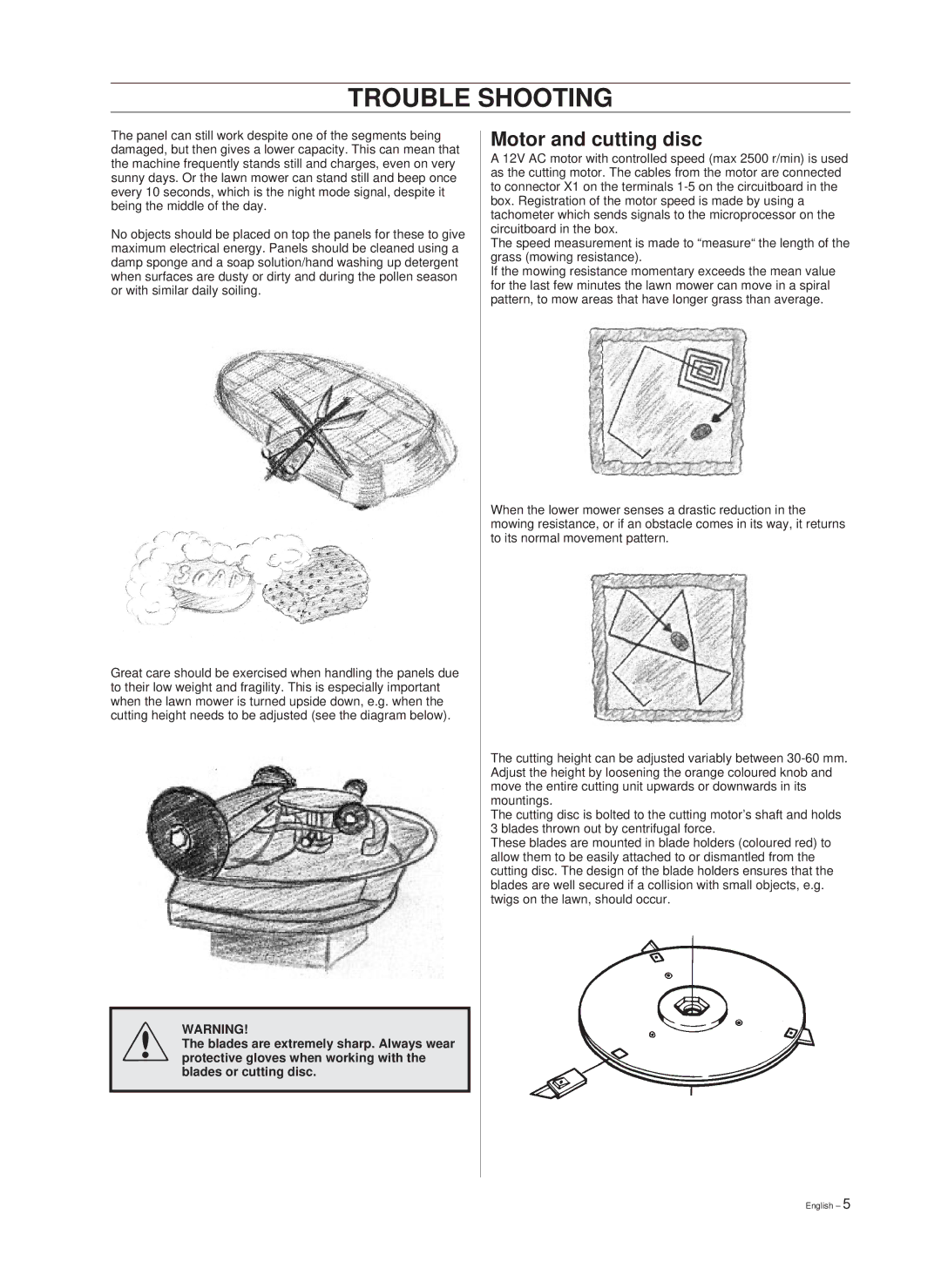
Hayter Mowers has long been synonymous with quality and innovation in the realm of lawn care, and their 101 88 90-26 model epitomizes this legacy. Designed for the discerning gardener and professional landscaper alike, this mower combines cutting-edge technology with robust features to enhance your mowing experience.One of the standout characteristics of the Hayter 101 88 90-26 is its powerful engine. Featuring a reliable Briggs & Stratton motor, this model provides ample power to tackle various grass conditions, from lush lawns to tougher terrains. The engine is designed not only for performance but also for efficiency, minimizing fuel consumption while maximizing output.
Another defining feature of the 101 88 90-26 is its cutting width. With a generous 26-inch blade, this mower can cover large areas quickly, reducing the time spent on mowing without compromising on the quality of the cut. The precision-engineered blades ensure a clean cut, promoting healthier grass growth and a more attractive lawn.
The Hayter 101 88 90-26 also boasts an adjustable cutting height system, allowing users to customize the grass length according to their preferences. With a range of settings, the mower adapts effortlessly to different types of grass and yard conditions, whether you prefer a close cut for a formal garden or a longer length for a more natural look.
Durability is another hallmark of Hayter mowers, and the 101 88 90-26 is built with robust materials designed to withstand the rigors of regular use. The steel chassis not only adds to the mower's longevity but also contributes to its stability during operation, ensuring a steady and balanced performance.
Technologically, this mower is equipped with an intuitive starting system that minimizes effort and enhances user experience. The easy-start feature means you can get to work quickly without fumbling with complicated mechanisms.
The mower’s ergonomic handles are adjustable and designed for comfort, reducing strain during extended use. User-friendly controls further enhance the operation, making it an ideal choice for both novice users and seasoned professionals.
In summary, the Hayter Mowers 101 88 90-26 is a powerful, efficient, and versatile lawn mower that combines advanced technology with user-friendly features. Its robust construction, adjustable settings, and ease of use make it a worthy investment for anyone looking to achieve a pristine lawn.

