H. Inspect the Appliance and Components
•Remove the contents from the carton labeled “Burner”. Attached to the burner are tags identifying the manufacturer name, serial number, model number (including gas log size), BTU ratings, gas type, etc.
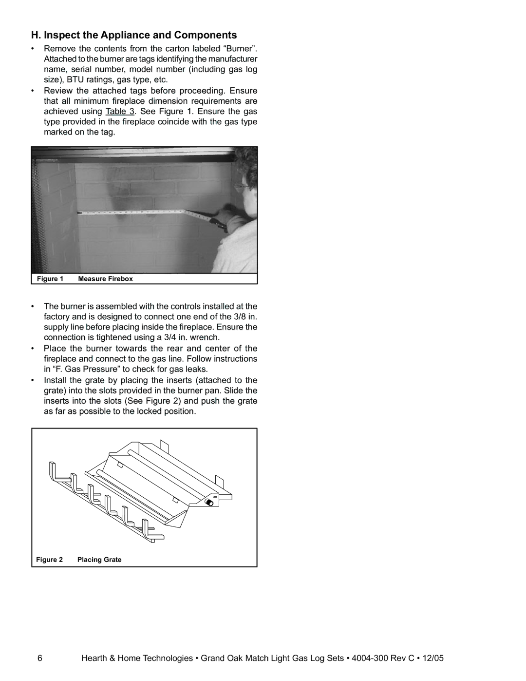
•Review the attached tags before proceeding. Ensure that all minimum fi replace dimension requirements are achieved using Table 3. See Figure 1. Ensure the gas type provided in the fi replace coincide with the gas type marked on the tag.
Figure 1 Measure Firebox
•The burner is assembled with the controls installed at the factory and is designed to connect one end of the 3/8 in. supply line before placing inside the fi replace. Ensure the connection is tightened using a 3/4 in. wrench.
•Place the burner towards the rear and center of the fi replace and connect to the gas line. Follow instructions in “F. Gas Pressure” to check for gas leaks.
•Install the grate by placing the inserts (attached to the grate) into the slots provided in the burner pan. Slide the inserts into the slots (See Figure 2) and push the grate as far as possible to the locked position.
Figure 2 | Placing Grate |
6Hearth & Home Technologies • Grand Oak Match Light Gas Log Sets •