Table 1 for Factory Built Fireplaces
Free Opening Area (in square inches) of Chimney Damper for Venting combustion
Chimney Ht. | ODGO 324 | ODGO 324 |
(Feet)* | LP Gas | Natural Gas |
10 | 35.3 | not approved |
|
|
|
15 | 26.4 | 38.5 |
|
|
|
20 | 22.1 | 31.2 |
25 | 18.1 | 27.3 |
|
|
|
30 | 17.3 | 24.6 |
35 | 15.9 | 22.1 |
|
|
|
Table 2 for Masonary Built
Fireplaces
Free Opening Area (in square inches) of Chimney Damper for Venting combustion
Chimney Ht. | ODGO 324 | ODGO3 24 |
(Feet)* | LP Gas | Natural Gas |
6 | 49.2 | 64 |
|
|
|
8 | 45.5 | 59.7 |
|
|
|
10 | 41.7 | 54.3 |
15 | 37.7 | 48.8 |
|
|
|
20 | 34.3 | 44.4 |
30 | 31.2 | 40.3 |
Table 3 for Minimum Fireplace Dimensions
| Front |
|
| Rear | Natural | Propane |
Log Set | Opening | Depth | Height | Width | BTU | BTU |
ODGO324 | 34 in. | 23 in. | 22 in. | 22 in. | 88,000 | 80,000 |
G. Inspect the Appliance and Components
•Remove the contents from the carton labeled “Burner”. Attached to the burner are tags identifying the manufacturer name, serial number, model number (including gas log size), BTU ratings, gas type, etc.
•Review the attached tags before proceeding. Ensure that all minimum fireplace dimension requirements are achieved using Table 3 . See Figure 1. Ensure the gas type provided in the fireplace coincide with the gas type marked on the tag.
Figure 1 Measure Firebox
•The burner is assembled with the controls installed at the factory and is designed to connect one end of the 3/8 in. supply line before placing inside the fireplace. Ensure the connection is tightened using a 3/4 in. wrench.
•Place the burner towards the rear and center of the fireplace and connect to the gas line. Follow instructions in “F. Gas Pressure” to check for gas leaks.
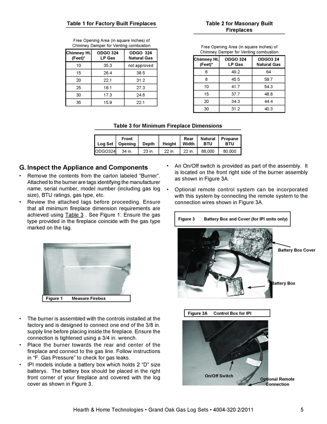
•IPI models include a battery box which holds 2 “D” size batterys. The battery box should be placed in the right front corner of your fireplace and covered with the log cover as shown in Figure 3.
•An On/Off switch is provided as part of the assembly. It is located on the front right side of the burner assembly as shown in Figure 3A.
•Optional remote control system can be incorporated with this system by connecting the remote system to the connection wires shown in Figure 3A.
Figure 3 Battery Box and Cover (for IPI units only)
Battery Box Cover
Battery Box
Figure 3A Control Box for IPI
On/Off Switch | Optional Remote |
| |
| Connection |
Hearth & Home Technologies • Grand Oak Gas Log Sets •