Component Identification and Function
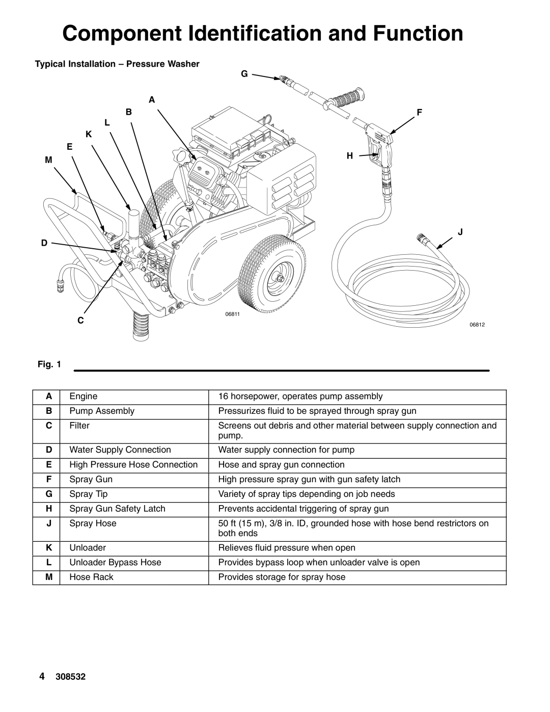
Typical Installation – Pressure Washer
G
A
BF
L
K
E
M![]() H
H
J
D ![]()
C
06811
06812
Fig. 1
A | Engine | 16 horsepower, operates pump assembly |
|
|
|
B | Pump Assembly | Pressurizes fluid to be sprayed through spray gun |
|
|
|
C | Filter | Screens out debris and other material between supply connection and |
|
| pump. |
|
|
|
D | Water Supply Connection | Water supply connection for pump |
|
|
|
E | High Pressure Hose Connection | Hose and spray gun connection |
|
|
|
F | Spray Gun | High pressure spray gun with gun safety latch |
|
|
|
G | Spray Tip | Variety of spray tips depending on job needs |
|
|
|
H | Spray Gun Safety Latch | Prevents accidental triggering of spray gun |
|
|
|
J | Spray Hose | 50 ft (15 m), 3/8 in. ID, grounded hose with hose bend restrictors on |
|
| both ends |
|
|
|
K | Unloader | Relieves fluid pressure when open |
|
|
|
L | Unloader Bypass Hose | Provides bypass loop when unloader valve is open |
|
|
|
M | Hose Rack | Provides storage for spray hose |
|
|
|
4308532
