[2] DC voltage to be supplied

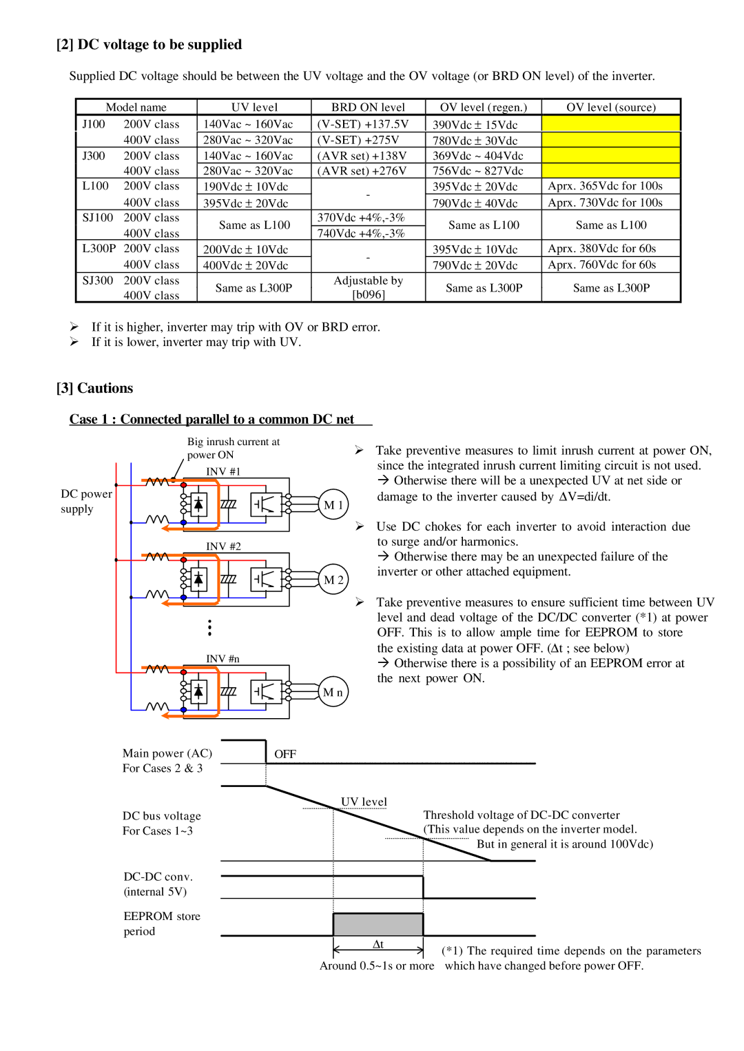
Supplied DC voltage should be between the UV voltage and the OV voltage (or BRD ON level) of the inverter.

Model name

UV level

BRD ON level

OV level (regen.)

OV level (source)

J100

200V class

140Vac ~ 160Vac

(V-SET) +137.5V

390Vdc ± 15Vdc


400V class

280Vac ~ 320Vac

(V-SET) +275V

780Vdc ± 30Vdc


J300

200V class

140Vac ~ 160Vac

(AVR set) +138V

369Vdc ~ 404Vdc


400V class

280Vac ~ 320Vac

(AVR set) +276V

756Vdc ~ 827Vdc


L100

200V class

190Vdc ± 10Vdc

-

395Vdc ± 20Vdc

Aprx. 365Vdc for 100s


400V class

395Vdc ± 20Vdc

790Vdc ± 40Vdc

Aprx. 730Vdc for 100s


SJ100

200V class

Same as L100

370Vdc +4%,-3%

Same as L100

Same as L100


400V class

740Vdc +4%,-3%


L300P

200V class

200Vdc ± 10Vdc

-

395Vdc ± 10Vdc

Aprx. 380Vdc for 60s


400V class

400Vdc ± 20Vdc

790Vdc ± 20Vdc

Aprx. 760Vdc for 60s


SJ300

200V class

Same as L300P

Adjustable by

Same as L300P

Same as L300P


400V class

[b096]


ØIf it is higher, inverter may trip with OV or BRD error.

ØIf it is lower, inverter may trip with UV.

[3]Cautions

Case 1 : Connected parallel to a common DC net

Big inrush current at power ON

INV #1

ØTake preventive measures to limit inrush current at power ON, since the integrated inrush current limiting circuit is not used. à Otherwise there will be a unexpected UV at net side or

DC power supply

M 1

damage to the inverter caused by ΔV=di/dt.

INV #2

ØUse DC chokes for each inverter to avoid interaction due to surge and/or harmonics.

à Otherwise there may be an unexpected failure of the

M 2

inverter or other attached equipment.

INV #n

ØTake preventive measures to ensure sufficient time between UV level and dead voltage of the DC/DC converter (*1) at power OFF. This is to allow ample time for EEPROM to store

the existing data at power OFF. (Δt ; see below)

àOtherwise there is a possibility of an EEPROM error at the next power ON.

M n

Main power (AC) For Cases 2 & 3

DC bus voltage For Cases 1~3

DC-DC conv. (internal 5V)

EEPROM store period

OFF

UV level

Threshold voltage of DC-DC converter (This value depends on the inverter model.

But in general it is around 100Vdc)


Δt

(*1) The required time depends on the parameters


Around 0.5~1s or more which have changed before power OFF.

Page 3
Image 3
Hitachi AN091802-1 instruction manual DC voltage to be supplied, Case 1 Connected parallel to a common DC net

AN091802-1 specifications

The Hitachi AN091802-1 is a high-performance semiconductor device recognized for its versatile applications in various electronic systems. This integrated circuit (IC) is predominantly used in power management and control systems, making it a critical component in modern electronic designs.

One of the main features of the AN091802-1 is its exceptional energy efficiency. It employs advanced power management technologies that allow devices to operate with minimal power wastage, making it an ideal choice for battery-operated devices and renewable energy systems. With a low quiescent current, the IC ensures longevity and reliability, especially in applications where power conservation is paramount.

In terms of its performance characteristics, the AN091802-1 boasts a wide input voltage range. This versatility permits compatibility with numerous voltage supply scenarios, expanding its usability in various applications, from consumer electronics to industrial equipment. Additionally, the IC supports high switching frequencies, which enhances its responsiveness and efficiency in power conversion tasks.

The Hitachi AN091802-1 integrates several protection features that promote safe operation. These include over-voltage protection, under-voltage lockout, and thermal shutdown capabilities. These built-in safeguards are essential in preventing damage to the IC and the systems in which it is deployed, thereby enhancing overall system reliability.

Another key aspect of the AN091802-1 is its compact packaging. The design minimizes space requirements on PCBs, allowing for more efficient layouts. This compactness is particularly advantageous in applications where size is a constraint, such as wearable technology and portable devices.

Moreover, the IC employs advanced analog and digital control technologies which enable precise regulation and monitoring of output parameters. This level of control is vital in applications requiring stringent performance criteria and enhances the overall functionality of the electronic systems.

In summary, the Hitachi AN091802-1 is a feature-rich integrated circuit known for its energy efficiency, versatile voltage compatibility, robust protection mechanisms, and space-saving design. Its advanced technologies make it a reliable and effective component for various electronic applications, reflecting Hitachi's commitment to innovation in semiconductor solutions.