SPECIFICATIONS
Model | G18SE3 |
| G18SG2 | G23SF2 |
| G23U2 | G23SE2 |
| G23UB2 | |
Voltage (by areas)*1 |
|
|
| (110V, 220V, 230V, 240V) |
|
|
| |||
Input*1 | 2300 W |
| 2500 W | 2000 W | 2400 W, 2500 W | |||||
8500 |
|
| 6600 |
|
| |||||
| Outer dia. | 180 mm |
|
| 230 mm |
|
| |||
Wheel | Inner dia. |
|
|
|
| 22 mm |
|
|
| |
| Peripheral speed |
|
|
|
| 80 m/s |
|
|
| |
Weight*2 |
| 5.0 kg |
| 4.3 kg |
| 5.0 kg | ||||
Starting current limiter*3 |
| No | No |
| Yes | No |
| Yes | ||
*1 Be sure to check the nameplate on product as it is subject to change by areas.
*2 Weight: Only main body
*3 The starting current limiter produces the starting current to such an extent that a fuse (16A,
STANDARD ACCESSORIES |
| |
(1) | Wrench | 1 |
(2) | Side handle | 1 |
Depressed center wheels are not provided as standard | ||
accessories. |
| |
Standard accessories are subject to change without | ||
notice. |
| |
APPLICATIONS
◯Removal of casting fin and finishing of various types of steel, bronze and aluminum materials and castings.
◯Grinding of welded sections or sections cut by means of a cutting torch.
◯Grinding of synthetic resins, slate, brick, marble, etc.
◯Cutting of synthetic concrete, stone, brick, marble and similar materials.
PRIOR TO OPERATION
1.Power source
Ensure that the power source to be utilized conforms to the power requirements specified on the product nameplate.
2.Power switch
Ensure that the power switch is in the OFF position. If the plug is connected to a receptacle while the power switch is in the ON position, the power tool will start operating immediately, which could cause a serious accident.
3.Extension cord
When the work area is removed from the power source, use an extension cord of sufficient thickness and rated capacity. The extension cord should be kept as short as practicable.
4.Fitting and adjusting the wheel guard
The wheel guard is a protective device to prevent injury should the depressed center wheel shatter during operation. Ensure that the guard is properly fitted and fastened before commencing grinding operation.
[Adjusting the wheel guard, For G23SF2, G23U2 only]
◯By slightly loosening the setting screw, the wheel guard can be turned and set at any desired angle for maximum operational effectiveness.
◯Ensure that the setting screw is thoroughly tightened
after adjusting the wheel guard.
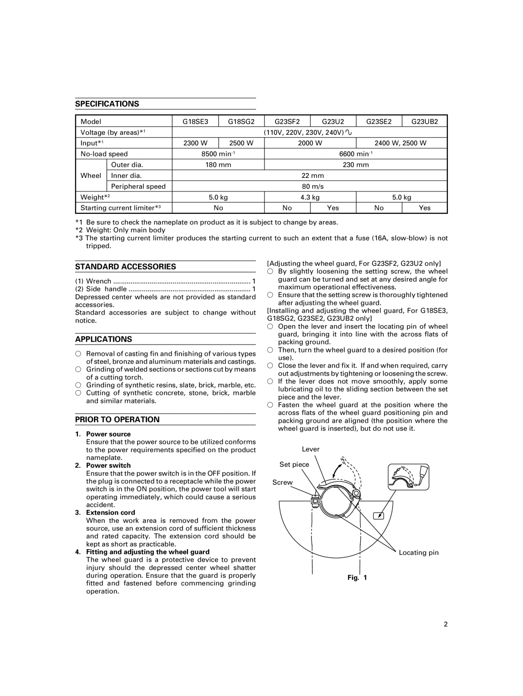
[Installing and adjusting the wheel guard, For G18SE3, G18SG2, G23SE2, G23UB2 only]
◯Open the lever and insert the locating pin of wheel guard, bringing it into line with the across flats of packing ground.
◯Then, turn the wheel guard to a desired position (for use).
◯Close the lever and fix it. If and when required, carry out adjustments by tightening or loosening the screw.
◯If the lever does not move smoothly, apply some lubricating oil to the sliding section between the set piece and the lever.
◯Fasten the wheel guard at the position where the across flats of the wheel guard positioning pin and packing ground are aligned (the position where the wheel guard is inserted), but do not use it.
Lever
Set piece
Screw
Locating pin
Fig. 1
2