Manuals
/
Hitachi
/
Household Appliance
/
Heat Pump
Hitachi
SERIES F
manual
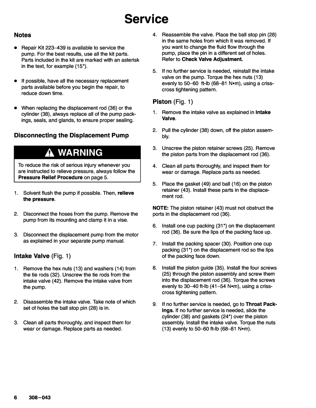
Service, Disconnecting the Displacement Pump, Intake Valve Fig, Piston Fig
Models:
210-208
SERIES F
1
6
12
12
Download
12 pages
11.47 Kb
3
4
5
6
7
8
9
10
Warranty
Setup/Operation
Check Valve Adjustment
Displacement Pump
Service
Technical Data
Page 6
Image 6
Page 5
Page 7
Page 6
Image 6
Page 5
Page 7
Contents
Rev. F Supersedes Rev. C and PCN D
INSTRUCTIONS-PARTSLIST
Model 210-208,Series F
READ AND KEEP FOR REFERENCE
Warning Symbol
Table of Contents
Symbols
Caution Symbol
cal attention
WRNING
INJECTION HAZARD
MOVING PRTS HZRD
FIRE AND EXPLOSION HAZARD
TOXIC FLUID HAZARD
Operation
Setup/Operation
Pressure Relief Procedure
General Information
Intake Valve Fig
Service
Disconnecting the Displacement Pump
Piston Fig
THROAT
PISTON
Service
Throat Packings Fig
Reconnecting the Displacement Pump
Check Valve Adjustment
Service
3843
36 15 16† 49 28 43 24 31 15 30
Parts
24 38 32 †18
39 †47
Manual Change Summary
Technical Data
Model 210-208,Series F Displacement Pump
Packing Conversion Kit
you 1-800-367-4023Toll Free
The Graco Warranty and Disclaimers
Graco Phone Number
WARRANTY
Top
Page
Image
Contents