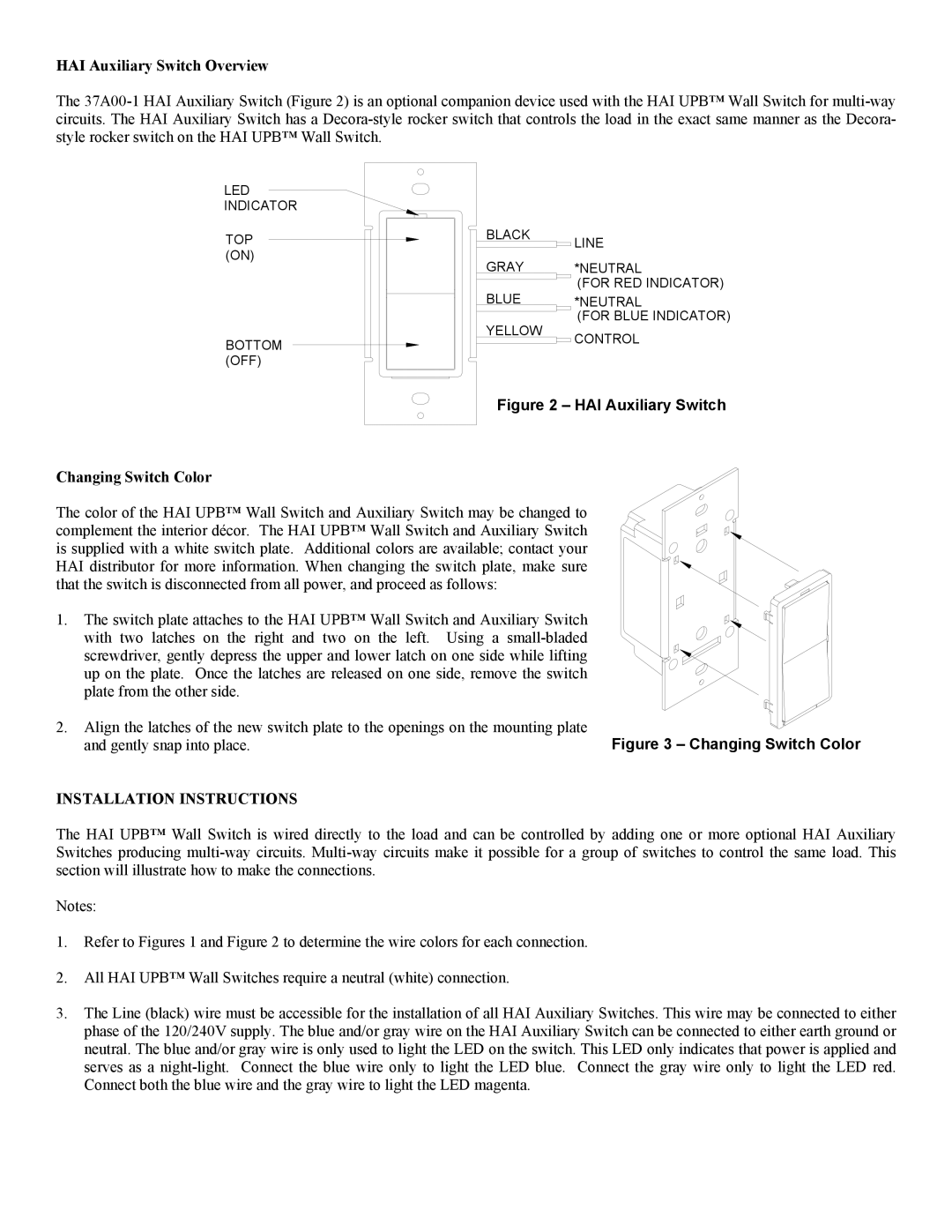
HAI Auxiliary Switch Overview
The
LED
INDICATOR
TOP | BLACK |
|
| LINE |
(ON) | GRAY |
|
| *NEUTRAL |
|
|
| ||
| BLUE |
|
| (FOR RED INDICATOR) |
|
|
| *NEUTRAL | |
|
|
|
| (FOR BLUE INDICATOR) |
YELLOW
BOTTOMCONTROL (OFF)
Figure 2 – HAI Auxiliary Switch
Changing Switch Color
The color of the HAI UPB™ Wall Switch and Auxiliary Switch may be changed to complement the interior décor. The HAI UPB™ Wall Switch and Auxiliary Switch is supplied with a white switch plate. Additional colors are available; contact your HAI distributor for more information. When changing the switch plate, make sure that the switch is disconnected from all power, and proceed as follows:
1. The switch plate attaches to the HAI UPB™ Wall Switch and Auxiliary Switch with two latches on the right and two on the left. Using a
2.Align the latches of the new switch plate to the openings on the mounting plate
and gently snap into place. | Figure 3 – Changing Switch Color |
INSTALLATION INSTRUCTIONS
The HAI UPB™ Wall Switch is wired directly to the load and can be controlled by adding one or more optional HAI Auxiliary Switches producing
Notes:
1.Refer to Figures 1 and Figure 2 to determine the wire colors for each connection.
2.All HAI UPB™ Wall Switches require a neutral (white) connection.
3.The Line (black) wire must be accessible for the installation of all HAI Auxiliary Switches. This wire may be connected to either phase of the 120/240V supply. The blue and/or gray wire on the HAI Auxiliary Switch can be connected to either earth ground or neutral. The blue and/or gray wire is only used to light the LED on the switch. This LED only indicates that power is applied and serves as a