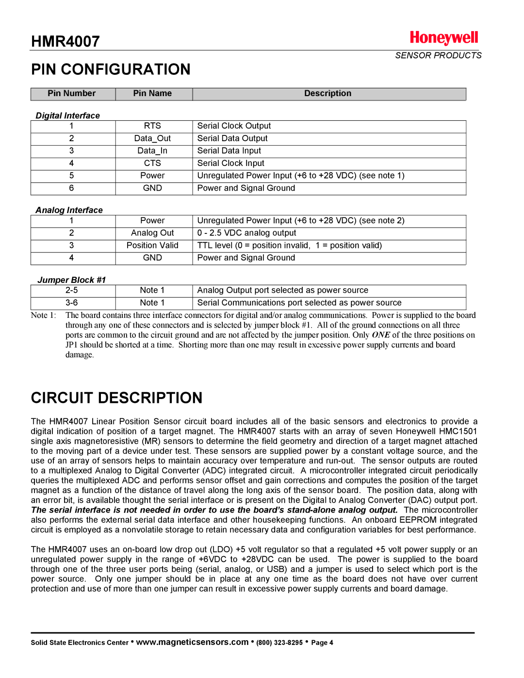
HMR4007 specifications
The Honeywell HMR4007 is an advanced sensor designed for precision measurement in various industrial applications. This device is celebrated for its robust performance and reliability, making it a favored choice among engineers and system designers.One of the main features of the HMR4007 is its high accuracy in measuring humidity and temperature, providing precise readings essential for maintaining optimal conditions in controlled environments. The sensor operates effectively across a wide temperature range, ensuring versatility for multiple applications. It is designed with a patented sensor technology that enhances its ability to withstand harsh conditions while maintaining accuracy.
In addition to high precision, the HMR4007 boasts a rapid response time, allowing it to quickly adapt to changes in the environment. This responsiveness is crucial in applications requiring real-time monitoring and control, such as in HVAC systems and environmental monitoring.
The device also integrates seamlessly with various communication protocols. This feature enables easy integration into existing systems and enhances its adaptability in different setups. Users can use standard interfaces for simple installation and maintenance, which reduces downtime and enhances operational efficiency.
Another significant characteristic of the Honeywell HMR4007 is its durability. Constructed with high-quality materials, the sensor is built to withstand the rigors of industrial environments, making it a reliable choice for long-term applications. Its rugged design ensures longevity, reducing the need for frequent replacements.
The sensor's compact size makes it suitable for applications with limited space, while its lightweight design ensures easy installation. Furthermore, the HMR4007 is designed for low power consumption, making it cost-effective in the long run.
In summary, the Honeywell HMR4007 stands out due to its high accuracy, rapid response time, flexible communication options, and robust durability. These features make it an ideal sensor for a variety of industries looking to maintain precise environmental conditions. Its advanced technology and reliability ensure that it meets the demanding needs of modern industrial applications, positioning it as a valuable tool for professionals in the field.

