
Wet/Dry Vac specifications
The Hoover Wet/Dry Vac is a versatile cleaning tool designed to tackle a wide range of messes in both residential and commercial settings. Known for its durability and efficiency, this vacuum cleaner stands out due to its innovative features and robust design.One of the key features of the Hoover Wet/Dry Vac is its powerful motor that offers impressive suction capabilities. It effectively picks up both wet and dry debris, making it ideal for spills, construction debris, and everyday dirt in your home or workspace. The ability to handle liquids sets it apart from standard vacuums, allowing users to clean up quickly and efficiently without the need for multiple devices.
A notable technological advancement in the Hoover Wet/Dry Vac is its multi-stage filtration system. This system is designed to capture fine dust and particles, ensuring that the air expelled from the vacuum is cleaner than the air that was drawn in. The washable filter not only contributes to better air quality but is also a cost-effective solution for users who wish to reduce their consumption of disposable filters.
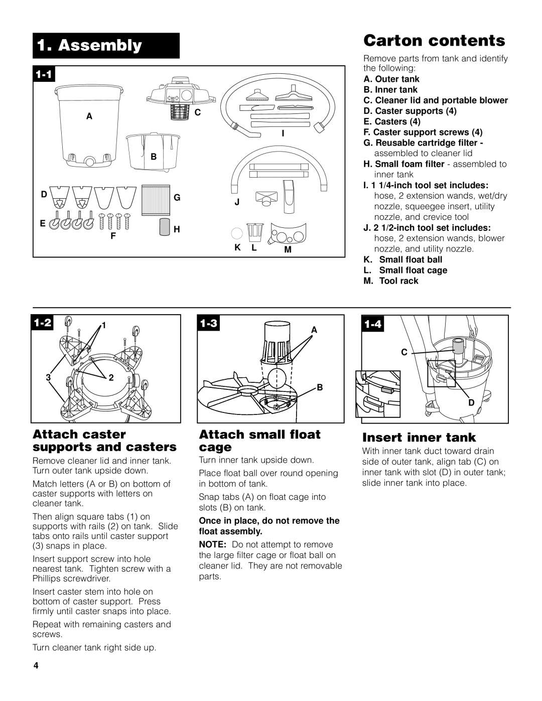
Additionally, the Hoover Wet/Dry Vac comes equipped with a variety of accessories that enhance its functionality. These may include extension wands, floor nozzles, and specialized brushes for different cleaning tasks. This array of attachments allows users to customize their cleaning experience, whether they are vacuuming carpets, cleaning hard floors, or tackling tight spaces.
Another characteristic of the Hoover Wet/Dry Vac is its large-capacity tank. With ample space for both liquid and dry debris, users can clean larger areas without frequently emptying the tank. This feature is particularly advantageous for professionals who need to maintain efficiency on the job.
The unit is also designed for mobility and ease of use. Many models include sturdy wheels and ergonomic handles, making it easy to transport from one location to another. Some versions feature a compact design for convenient storage, making them perfect for homes with limited space.
Finally, the Hoover Wet/Dry Vac is backed by a reputation for reliability and performance, making it a go-to choice for those seeking an effective cleaning solution. With its combination of power, versatility, and user-friendly design, it remains a top contender in the market for wet/dry vacuums, catering to both everyday households and demanding professional environments.