Installation
Assembly
GB
Before proceeding with the assembly operations, remove the grease filters so that the hood is easier to handle (for the instructions see the paragraph “Cleaning the grease filters” in the chapter on “Maintenance”).
Fixing to the wall
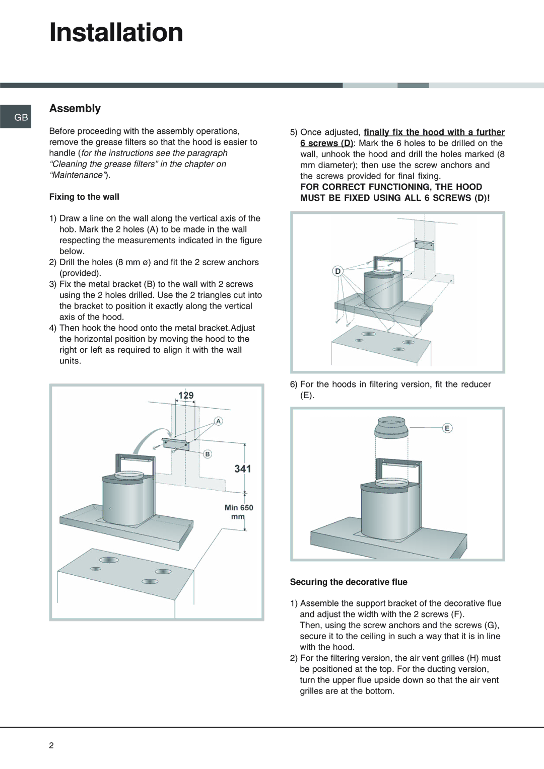
1)Draw a line on the wall along the vertical axis of the hob. Mark the 2 holes (A) to be made in the wall respecting the measurements indicated in the figure below.
2)Drill the holes (8 mm ø) and fit the 2 screw anchors (provided).
3)Fix the metal bracket (B) to the wall with 2 screws using the 2 holes drilled. Use the 2 triangles cut into the bracket to position it exactly along the vertical axis of the hood.
4)Then hook the hood onto the metal bracket.Adjust the horizontal position by moving the hood to the right or left as required to align it with the wall units.
5)Once adjusted, finally fix the hood with a further 6 screws (D): Mark the 6 holes to be drilled on the wall, unhook the hood and drill the holes marked (8 mm diameter); then use the screw anchors and the screws provided for final fixing.
FOR CORRECT FUNCTIONING, THE HOOD MUST BE FIXED USING ALL 6 SCREWS (D)!
6)For the hoods in filtering version, fit the reducer
(E).
Securing the decorative flue
1)Assemble the support bracket of the decorative flue and adjust the width with the 2 screws (F).
Then, using the screw anchors and the screws (G), secure it to the ceiling in such a way that it is in line with the hood.
2)For the filtering version, the air vent grilles (H) must be positioned at the top. For the ducting version, turn the upper flue upside down so that the air vent grilles are at the bottom.
2