System Board
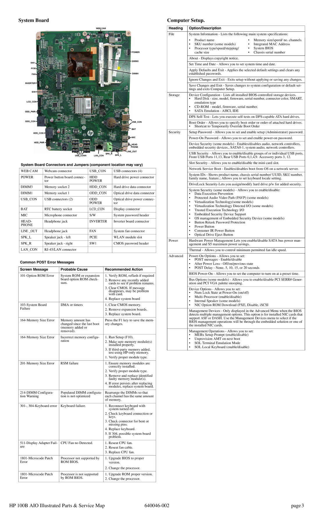
System Board Connectors and Jumpers (component location may vary)
WEB CAM | Webcam connector | USB_CON | USB connectors (4) |
|
|
|
|
POWER | Power button board connec- | HDD | Hard drive power connector |
| tor | POWER |
|
DIMM3 | Memory socket 2 | HDD_CON | Hard drive data connector |
|
|
|
|
DIMM1 | Memory socket 1 | ODD_CON | Optical drive data connector |
|
|
|
|
USB_CON | USB connectors (2) | ODD | Optical drive power connec- |
|
| POWER | tor |
|
|
|
|
BAT | RTC battery socket | LCD_CON | Display connector |
|
|
|
|
MIC | Microphone connector | S/W | System password header |
|
|
|
|
HEAD- | Headphone jack | INVERTER | Inverter board connector |
PHONE |
|
|
|
LINE _OUT | Headphone jack | FAN | System fan connector |
|
|
|
|
SPK_L | Speaker jack - left | PCIE | WLAN module slot |
|
|
|
|
SPK_R | Speaker jack - right | SW1 | CMOS password header |
|
|
|
|
LAN_CON |
|
| |
|
|
|
|
Common POST Error Messages
Screen Message | Probable Cause | Recommended Action | |
|
|
|
|
System ROM or expansion | 1. | Verify ROM, reflash if required | |
| board option ROM check- | 2. | Remove any recently added |
| sum. |
| cards to see if problem remains. |
|
| 3. | Clear CMOS. If message |
|
|
| disappears, may be problem |
|
|
| with card. |
|
| 4. | Replace system board |
|
|
|
|
DMA or timers | 1. | Clear CMOS memory. | |
Failure |
| 2. | Remove expansion boards. |
|
| 3. | Replace system board. |
|
|
| |
Memory amount has | Press the F1 key to save the mem- | ||
| changed since the last boot | ory changes. | |
| (memory added or |
|
|
| removed). |
|
|
Incorrect memory configu- | 1. | Run Setup (F10). | |
| ration | 2. | Make sure memory module(s) |
|
|
| installed properly. |
|
| 3. | If |
|
|
| test using |
|
| 1. | Verify proper module type. |
|
|
|
|
RSM failure | 1. | Ensure memory modules are | |
|
|
| correctly installed. |
|
| 2. | Verify proper module type. |
|
| 3. | Remove and replace identified |
|
|
| faulty memory module(s). |
|
| 4. | If error persists after replacing |
|
|
| modules, replace system board. |
Populated DIMM configura- | Rearrange the DIMMs so that | ||
tion Warning | tion is not optimized | each channel has the same amount | |
|
| of memory. | |
|
|
|
|
Keyboard failure. | 1. | Reconnect keyboard with | |
|
|
| system turned off. |
|
| 2. | Check keyboard connection or |
|
|
| keys. |
|
| 3. | Check connector for bent or |
|
|
| missing pins. |
|
| 4. | Replace keyboard. |
|
| 5. | If 304, possible system board |
|
|
| problem. |
CPU Fan no Detected. | 1. | Reseat CPU fan. | |
ure |
| 2. | Reseat fan cable. |
|
| 3. | Replace CPU fan. |
|
|
|
|
Processor not supported by | 1. | Upgrade BIOS to proper | |
Error | ROM BIOS. |
| version. |
|
| 2. | Change the processor. |
|
|
|
|
Processor is not supported | 1. | Upgrade ROM proper version. | |
Error | by ROM BIOS. | 2. | Change the processor. |
|
|
|
|
Computer Setup.
Heading | Option/Description |
|
|
| |
|
|
| |||
File | System Information - Lists the following main system specifications: | ||||
| • | Product name | • | Memory size/speed/ no. channels |
|
|
| ||||
| • | SKU number (some models) | • | Integrated MAC Address |
|
| • | Processor type/speed/stepping/ | • | System BIOS |
|
|
| cache size | • | Chassis serial number |
|
|
|
|
|
| |
| About - Displays copyright notice. |
|
|
| |
|
|
| |||
| Set Time and Date - Allows you to set system time and date. | ||||
|
|
| |||
| Apply Defaults and Exit - Applies the selected default settings and clears any | ||||
| established passwords. |
|
|
| |
| Ignore Changes and Exit - Exits setup without applying or saving any changes. | ||||
|
|
| |||
| Save Changes and Exit - Saves changes to system configuration or default set- | ||||
| tings and exits Computer Setup. |
|
|
| |
Storage | Device Configuration - Lists all installed | ||||
| • Hard Disk - size, model, firmware, serial number, connector color, SMART, | ||||
|
| emulation type |
|
|
|
| • | ||||
| • SATA Emulation - AHCI, IDE |
|
|
| |
|
|
| |||
| DPS | ||||
|
|
| |||
| Boot Order - Allows you to specify boot order or order of attached hard drives. | ||||
| • Shortcut to Temporarily Override Boot Order | ||||
Security | Setup Password - Allows you to set and enable setup (Administrator) password. | ||||
|
|
| |||
| |||||
|
|
| |||
| Device Security (some models) - Enables/disables audio, network controllers, | ||||
| embedded security devices., | ||||
|
|
| |||
| USB Security - Allows you to enable/disable groups of or individual USB ports. | ||||
| Front USB Ports 11,13, Rear USB Ports 0,1,4,9. Accessory ports 3, 12. | ||||
| Slot Security - Allows you to enable/disable the mini card slot. | ||||
|
|
| |||
| Network Service Boot - Enables/disables boot from OS on a network server. | ||||
|
|
| |||
| System IDs - Shows product name, chassis serial number/ UUID, SKU number, | ||||
| family name, feature.; Allows you to set keyboard locale setting. | ||||
|
|
| |||
| DriveLock | ||||
|
|
| |||
| System Security (some models) - Allows you to enable/disable: | ||||
| • | Data Execution Prevention |
|
|
|
| • Protected Audio Video Path (PAVP) (some models) | ||||
| • | Virtualization Technology(some models) |
|
| |
| • Virtualization Technology Directed I/O (some models) | ||||
| • Trusted Execution Technology I/O |
|
|
| |
| • Embedded Security Device Support |
|
|
| |
| • OS management of Embedded Security Device (some models) | ||||
| • Button Retask Password Protection |
|
|
| |
| • | Power Button |
|
|
|
| • Consumer IR Power Button |
|
|
| |
| • Optical Drive Eject Button |
|
|
| |
|
|
| |||
Power | Hardware Power | ||||
| agement and S5 maximum power savings. |
|
| ||
| Thermal - Allows you to control minimum permitted fan idle speed. | ||||
|
|
|
|
| |
Advanced |
|
|
| ||
| • | POST messages - Enable/disable |
|
|
|
| • After Power Loss - Off/on/previous state |
|
| ||
| • POST Delay - None, 5, 10, 15, or 20 seconds | ||||
|
|
| |||
| BIOS | ||||
|
|
| |||
| Bus Options (some models) - Allows you to enable/disable PCI SERR# Gener- | ||||
| ation and PCI VGA palette snooping. |
|
|
| |
Device Options - Allows you to set:
•Num Lock State at
•
•Internal Speaker (some models)
•NIC Option ROM Download (PXE, Disable, iSCSI
Management Devices - Only displayed in the Advanced Menu when the BIOS detects multiple management options. This option is for installed NIC cards that support ASF or DASH. Use the Management Devices menu to select if the BIOS management operations will be through the embedded solution or one of the installed NIC cards.
Management Operations - Allows you to set:
•MEBx Setup Prompt (enable/disable)
•Unprovision AMT on next boot
•SOL Terminal Emulation Mode
•SOL Local Keyboard (enable/disable)
HP 100B AIO Illustrated Parts & Service Map | page 3 |