Datacom testing using the
HP 37732A telecom/datacom analyzer
Datacom specifications
Datacom interfaces: V.24,
Terminal emulation: DTE, DCE.
Timing modes: Synchronous from 50 b/s to 2.048 Mb/s; asynchronous from 50 b/s to 19.2 kb/s (except
V.24 breakout
Isolation switches: TD, RD, XTC, TC, RC, RTS, CTS, DTR, DSR, DCD, situated between drivers/receivers and interface connector.
Patch points and voltage sources.
V.11/V.35 activity indicators Data and clock: SD, RD, TT/
SCTE, ST/SCT, RT/SCR.
Control circuits: RS, CS,
TR/DTR, DM/DSR, RR/RLSD.
Synchronous mode
Clock sources: Internal
synthesizer, datacom interface. (Selectable clock inversion.) Interface clock rates: 50 b/s to 2.048 Mb/s, ± 10 ppm. Synthesizer rates: 1.2, 2.4, 4.8, 9.6, 14.4, 19.2, 48, 56, 64, 384, 256, 512 kb/s, 1.024, 1.984 Mb/s, variable (600 b/s to 2.048 Mb/s). V.24 rate limited to 128 kb/s.
Asynchronous mode
Rates: 50, 75, 110, 134.5, 150, 200, 300, 600 b/s; 1.2, 1.8, 2.4, 4.8, 7.2, 9.6, 19.2 kb/s.
Character length: 5, 6, 7 or
8 bits.
Parity: Odd, even, 0, 1 or none.
Stop bits: 1, 1.5 or 2.
Data polarity: Normal or inverse.
Error add: Single, variable 10− 2 to 10− 5.
Test patterns
PRBS: 63, 511, or 2047 bit, 215 − 1, 220 − 1.
Fixed: Permanent mark, alternating mark/space inversion, FOX message (asynchronous mode only).
Word:
Test period: Manual, timed interval (1 s to 100 days), bit interval (10n bits, n = 4 to 10).
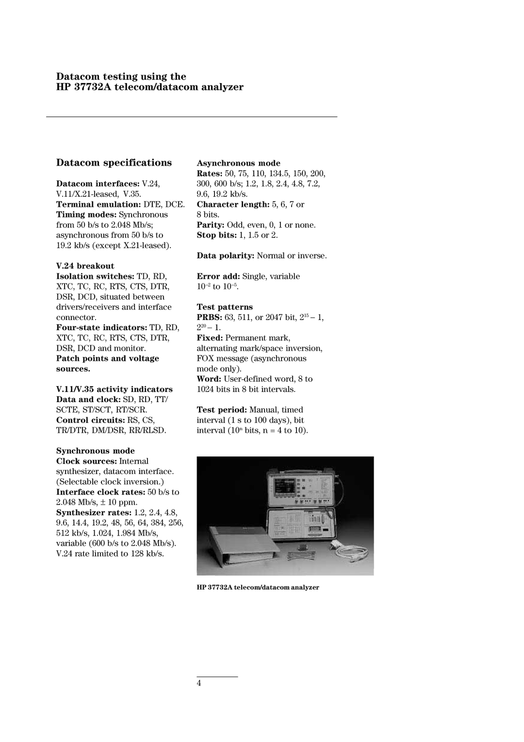
HP 37732A telecom/datacom analyzer
4