CAUTION: Before turning the display panel assembly upside down, make sure the work surface is clear of tools, screws, and any other foreign objects. Failure to follow this caution can result in damage to the display panel assembly.
1.Place the tablet on a flat surface, display panel side down, with the SD Card slot and volume control buttons toward you.
CAUTION: When inserting the plastic tool into the tablet as described in Step 2, make sure not to insert the tool into the volume control buttons area. Failure to follow this caution can result in damage to the tablet.
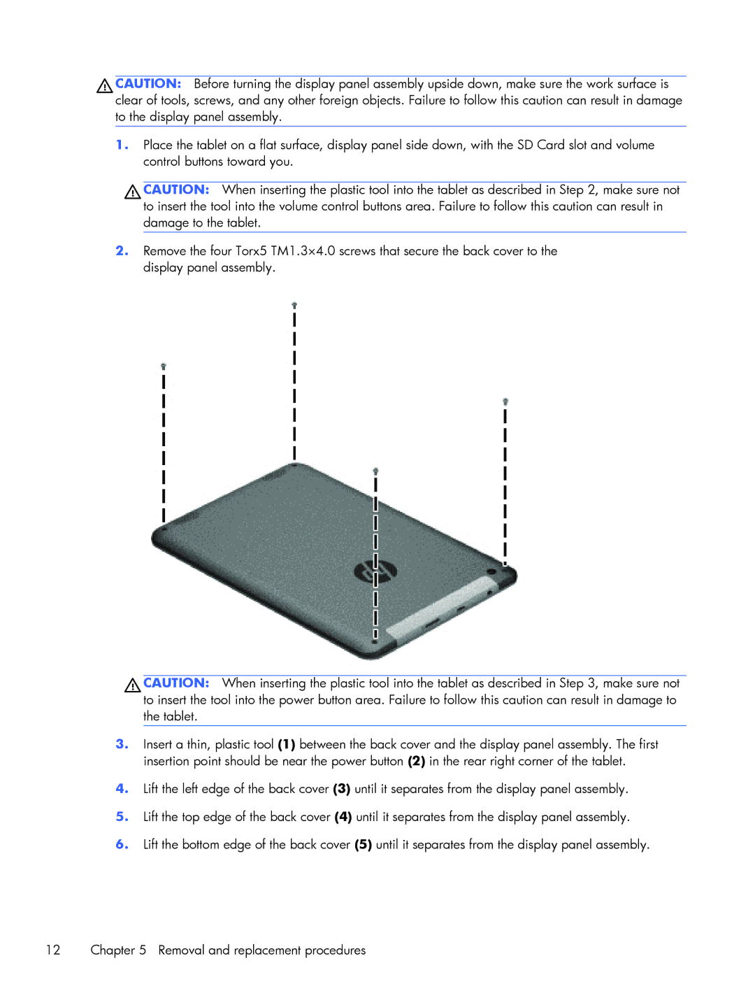
2.Remove the four Torx5 TM1.3×4.0 screws that secure the back cover to the display panel assembly.
CAUTION: When inserting the plastic tool into the tablet as described in Step 3, make sure not to insert the tool into the power button area. Failure to follow this caution can result in damage to the tablet.
3.Insert a thin, plastic tool (1) between the back cover and the display panel assembly. The first insertion point should be near the power button (2) in the rear right corner of the tablet.
4.Lift the left edge of the back cover (3) until it separates from the display panel assembly.
5.Lift the top edge of the back cover (4) until it separates from the display panel assembly.
6.Lift the bottom edge of the back cover (5) until it separates from the display panel assembly.
12 | Chapter 5 Removal and replacement procedures |