HP Insight Diagnostics

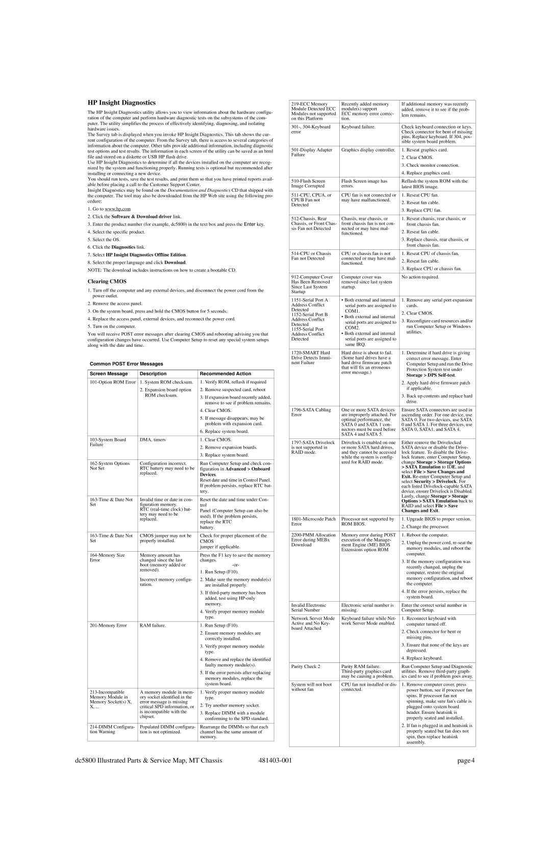
The HP Insight Diagnostics utility allows you to view information about the hardware configu- ration of the computer and perform hardware diagnostic tests on the subsystems of the com- puter. The utility simplifies the process of effectively identifying, diagnosing, and isolating hardware issues.

The Survey tab is displayed when you invoke HP Insight Diagnostics. This tab shows the cur- rent configuration of the computer. From the Survey tab, there is access to several categories of information about the computer. Other tabs provide additional information, including diagnostic test options and test results. The information in each screen of the utility can be saved as an html file and stored on a diskette or USB HP flash drive.

Use HP Insight Diagnostics to determine if all the devices installed on the computer are recog- nized by the system and functioning properly. Running tests is optional but recommended after installing or connecting a new device.

You should run tests, save the test results, and print them so that you have printed reports avail- able before placing a call to the Customer Support Center.

Insight Diagnostics may be found on the Documentation and Diagnostics CD that shipped with the computer. The tool may also be downloaded from the HP Web site using the following pro- cedure:

1.Go to www.hp.com

2.Click the Software & Download driver link.

3.Enter the product number (for example, dc5800) in the text box and press the Enter key.

4.Select the specific product.

5.Select the OS.

6.Click the Diagnostics link.

7.Select HP Insight Diagnostics Offline Edition.

8.Select the proper language and click Download.

NOTE: The download includes instructions on how to create a bootable CD.

Clearing CMOS

1.Turn off the computer and any external devices, and disconnect the power cord from the power outlet.

2.Remove the access panel.

3.On the system board, press and hold the CMOS button for 5 seconds.

4.Replace the access panel, external devices, and reconnect the power cord.

5.Turn on the computer.

You will receive POST error messages after clearing CMOS and rebooting advising you that configuration changes have occurred. Use Computer Setup to reset any special system setups along with the date and time.

Common POST Error Messages

Screen Message

Description

Recommended Action


101-Option ROM Error

1. System ROM checksum.

1.

Verify ROM, reflash if required


2. Expansion board option

2.

Remove suspected card, reboot


ROM checksum.

3.

If expansion board recently added,


remove to see if problem remains.


4.

Clear CMOS.


5.

If message disappears, may be


problem with expansion card.


6.

Replace system board.


103-System Board

DMA, timers

1.

Clear CMOS.

Failure


2.

Remove expansion boards.


3.

Replace system board.


162-System Options

Configuration incorrect.

Run Computer Setup and check con-

Not Set

RTC battery may need to be

figuration in Advanced > Onboard


replaced.

Devices.


Reset date and time in Control Panel.


If problem persists, replace RTC bat-


tery.


163-Time & Date Not

Invalid time or date in con-

Reset the date and time under Con-

Set

figuration memory.

trol


RTC (real-time clock) bat-

Panel (Computer Setup can also be


tery may need to be


used). If the problem persists,


replaced.


replace the RTC


battery.


163-Time & Date Not

CMOS jumper may not be

Check for proper placement of the

Set

properly installed.

CMOS


jumper if applicable.


164-Memory Size

Memory amount has

Press the F1 key to save the memory

Error

changed since the last

changes.


boot (memory added or


-or-


removed).

1.

Run Setup (F10).


Incorrect memory configu-

2.

Make sure the memory module(s)


ration.


are installed properly.


3.

If third-party memory has been


added, test using HP-only


memory.


4.

Verify proper memory module


type.


201-Memory Error

RAM failure.

1.

Run Setup (F10).


2.

Ensure memory modules are


correctly installed.


3.

Verify proper memory module


type.


4.

Remove and replace the identified


faulty memory module(s).


5.

If the error persists after replacing


memory modules, replace the


system board.


213-Incompatible

A memory module in mem-

1.

Verify proper memory module

Memory Module in

ory socket identified in the


type.

Memory Socket(s) X,

error message is missing

2.

Try another memory socket.

X, ...

critical SPD information, or


is incompatible with the

3.

Replace DIMM with a module


chipset.


conforming to the SPD standard.


214-DIMM Configura-

Populated DIMM configura-

Rearrange the DIMMs so that each

tion Warning

tion is not optimized.

channel has the same amount of


memory.


219-ECC Memory

Recently added memory

If additional memory was recently

Module Detected ECC

module(s) support

added, remove it to see if the prob-

Modules not supported

ECC memory error correc-

lem remains.

on this Platform

tion.


301-, 304-Keyboard

Keyboard failure.

Check keyboard connection or keys.

error


Check connector for bent of missing


pins. Replace keyboard. If 304, pos-


sible system board problem.


501-Display Adapter

Graphics display controller.

1.

Reseat graphics card.

Failure


2.

Clear CMOS.


3.

Check monitor connection.


4.

Replace graphics card.


510-Flash Screen

Flash Screen image has

Reflash the system ROM with the

Image Corrupted

errors.

latest BIOS image.


511-CPU, CPUA, or

CPU fan is not connected or

1.

Reseat CPU fan.

CPUB Fan not

may have malfunctioned.

2.

Reseat fan cable.

Detected


3.

Replace CPU fan.


512-Chassis, Rear

Chassis, rear chassis, or

1.

Reseat chassis, rear chassis, or

Chassis, or Front Chas-

front chassis fan is not con-


front chassis fan.

sis Fan not Detected

nected or may have mal-

2.

Reseat fan cable.


functioned.


3.

Replace chassis, rear chassis, or


front chassis fan.


514-CPU or Chassis

CPU or chassis fan is not

1.

Reseat CPU of chassis fan.

Fan not Detected

connected or may have mal-

2.

Reseat fan cable.


functioned.


3.

Replace CPU or chassis fan.


912-Computer Cover

Computer cover was

No action required.

Has Been Removed

removed since last system


Since Last System

startup.


Startup


1151-Serial Port A

• Both external and internal

1.

Remove any serial port expansion

Address Conflict

serial ports are assigned to


cards.

Detected

COM1.

2.

Clear CMOS.

1152-Serial Port B

• Both external and internal

Address Conflict

3.

Reconfigure card resources and/or

serial ports are assigned to

Detected


run Computer Setup or Windows

COM2.


1155-Serial Port


utilities.

Address Conflict

• Both external and internal


Detected

serial ports are assigned to


same IRQ.


1720-SMART Hard

Hard drive is about to fail.

1.

Determine if hard drive is giving

Drive Detects Immi-

(Some hard drives have a


correct error message. Enter

nent Failure

hard drive firmware patch


Computer Setup and run the Drive


that will fix an erroneous


Protection System test under


error message.)


Storage > DPS Self-test.


2.

Apply hard drive firmware patch


if applicable.


3.

Back up contents and replace hard


drive.


1796-SATA Cabling

One or more SATA devices

Ensure SATA connectors are used in

Error

are improperly attached. For

ascending order. For one device, use


optimal performance, the

SATA 0. For two devices, use SATA


SATA 0 and SATA 1 con-

0 and SATA 1. For three devices, use


nectors must be used before

SATA 0, SATA1, and SATA 4.


SATA 4 and SATA 5.


1797-SATA Drivelock

Drivelock is enabled on one

Either remove the Drivelocked

is not supported in

or more SATA hard drives,

SATA device or disable the Drive-

RAID mode.

and they cannot be accessed

lock feature. To disable the Drive-


while the system is config-

lock feature, enter Computer Setup,


ured for RAID mode.

change Storage > Storage Options


> SATA Emulation to IDE, and


select File > Save Changes and


Exit. Re-enter Computer Setup and


select Security > Drivelock. For


each listed Drivelock-capable SATA


device, ensure Drivelock is Disabled.


Lastly, change Storage > Storage


Options > SATA Emulation back to


RAID and select File > Save


Changes and Exit.


1801-Microcode Patch

Processor not supported by

1.

Upgrade BIOS to proper version.

Error

ROM BIOS.

2.

Change the processor.


2200-PMM Allocation

Memory error during POST

1.

Reboot the computer.

Error during MEBx

execution of the Manage-

2.

Unplug the power cord, re-seat the

Download

ment Engine (ME) BIOS


memory modules, and reboot the


Extensions option ROM


computer.


3.

If the memory configuration was


recently changed, unplug the


computer, restore the original


memory configuration, and reboot


the computer.


4.

If the error persists, replace the


system board.


Invalid Electronic

Electronic serial number is

Enter the correct serial number in

Serial Number

missing.

Computer Setup.


Network Server Mode

Keyboard failure while Net-

1.

Reconnect keyboard with

Active and No Key-

work Server Mode enabled.


computer turned off.

board Attached


2.

Check connector for bent or


missing pins.


3.

Ensure that none of the keys are


depressed.


4.

Replace keyboard.


Parity Check 2

Parity RAM failure.

Run Computer Setup and Diagnostic


Third-party graphics card

utilities. Remove third-party graph-


may be causing a problem.

ics card to see if problem goes away.


System will not boot

CPU fan not installed or dis-

1.

Remove computer cover, press

without fan

connected.


power button, see if processor fan


spins. If processor fan not


spinning, make sure fan's cable is


plugged onto system board


header. Ensure heatsink is


properly seated and installed.


2.

If fan is plugged in and heatsink is


properly seated but fan does not


spin, then replace heatsink


assembly.


dc5800 Illustrated Parts & Service Map, MT Chassis

481403-001

page 4

Page 4
Image 4
HP dc5800 manual HP Insight Diagnostics, Clearing Cmos

dc5800 specifications

The HP dc5800 is a compact desktop PC that has gained popularity in the business and educational sectors due to its solid build, affordability, and reliability. Introduced as part of HP’s dc series, it is designed to meet the demands of everyday computing tasks while offering enough power to handle more intensive applications when needed.

One of the standout features of the HP dc5800 is its sleek and functional design. With its small form factor, the dc5800 can easily fit into limited office spaces, providing flexibility for various workspace configurations. The chassis is built for easy accessibility, allowing users to upgrade components without hassle.

The dc5800 is powered by an Intel Core 2 Duo processor, which delivers excellent performance for multitasking and productivity applications. This dual-core architecture allows the system to efficiently handle everyday tasks such as word processing, spreadsheet management, and internet browsing. The pc supports a range of memory configurations, with up to 8GB of DDR2 RAM, ensuring smooth operation even when running multiple applications concurrently.

In terms of storage, the HP dc5800 offers a variety of hard drive options, ranging from traditional hard disk drives (HDDs) to faster solid-state drives (SSDs). This gives users the flexibility to choose based on their performance needs and budget. The system also includes multiple USB ports, an integrated audio solution, and network capability, making it well-suited for a connected office environment.

The onboard graphics solution provides adequate performance for standard business applications and light multimedia use, while the option to add discrete graphics cards allows for enhanced visual performance when required.

Another notable characteristic is the dc5800's energy efficiency. Designed with compliance to Energy Star standards, it consumes less power compared to older models, contributing to lower operational costs and a reduced carbon footprint.

Finally, HP offers a suite of security features, including a user password and the ability to disable USB ports to prevent data leaks, making the dc5800 a suitable choice for organizations that prioritize data security.

In summary, the HP dc5800 is a reliable, efficient, and compact desktop that combines essential features and technologies to support a variety of business and educational applications. Its performance, scalability, and energy efficiency make it a worthwhile investment for those looking for a dependable computing solution.