Boards
Boards, Memory, Processors
System boards (include replacement thermal material)
1 | System board for use in models without Windows 8 | |
|
|
|
* | System board for use in models with Windows 8 Standard | |
|
|
|
* | System board for use in models with Windows 8 Professional | |
|
|
|
* | System board for use in models with NetClone | |
|
|
|
2 | Converter board | |
|
|
|
3 | Sidekey board | |
|
|
|
4 | Webcam, 1.3MP with analog microphone | |
|
|
|
* | Memory module, 2 GB | |
|
|
|
* | Memory module, 4 GB | |
|
|
|
* | Memory module, 8 GB | |
|
|
|
Processors (include replacement thermal grease) |
| |
|
|
|
* | Intel Core i7 3770s processor, 3.1 GHz | |
|
|
|
* | Intel Core i5 3570 processor, 3.4 GHz | |
|
|
|
* | Intel Core i5 3475s processor, 2.9 GHz | |
|
|
|
* | Intel Core i5 3470s processor, 2.9 GHz | |
|
|
|
* | Intel Core i3 2130 processor, 3.4 GHz | |
|
|
|
* | Intel Core i3 2120 processor, 3.3 GHz | |
|
|
|
* | Intel Pentium | |
|
|
|
* | Intel Pentium | |
|
|
|
* | Intel Pentium | |
|
|
|
* | Intel Celeron G550 processor, 2.6 GHz | |
|
|
|
* | Intel Celeron G540 processor, 2.5 GHz | |
|
|
|
* | Intel Celeron G460 processor, 1.8 GHz | |
|
|
|
* Not shown
Miscellaneous Parts
Password Security and CMOS
Establishing a Setup or Power-On password
1.Turn on or restart the computer.
2.As soon as the computer turns on, press the Esc key while “Press the ESC key for Startup Menu” message is displayed at the bottom of the screen.
3.Press the F10 key to enter Computer Setup.
4.To establish Setup password, select Security > Setup Password and follow the instructions.
- or -
To establish a
5.Before exiting, click File > Save Changes and Exit.
Resetting a Setup or Power-On password
1.Turn off the computer and disconnect the power cord from the power outlet.
2.Remove the access panel.
3.On the system board, locate the header labeled PW.
4.Remove the jumper from the header.
5.Replace the jumper.
6.Replace the access panel and reconnect the power cord.
7.Turn on the computer and allow it to start.
Resetting CMOS
1.Turn off the computer and disconnect the power cord from the power outlet.
2.Remove the access panel.
3.On the system board, locate the header labeled CMOS.
4.Remove the jumper and place it on pins 1 and 2.
5.Wait for three seconds, and then replace the jumper to its original position (pins 2 and 3).
6.Replace the access panel and reconnect the power cord.
7.Turn on the computer and allow it to start.
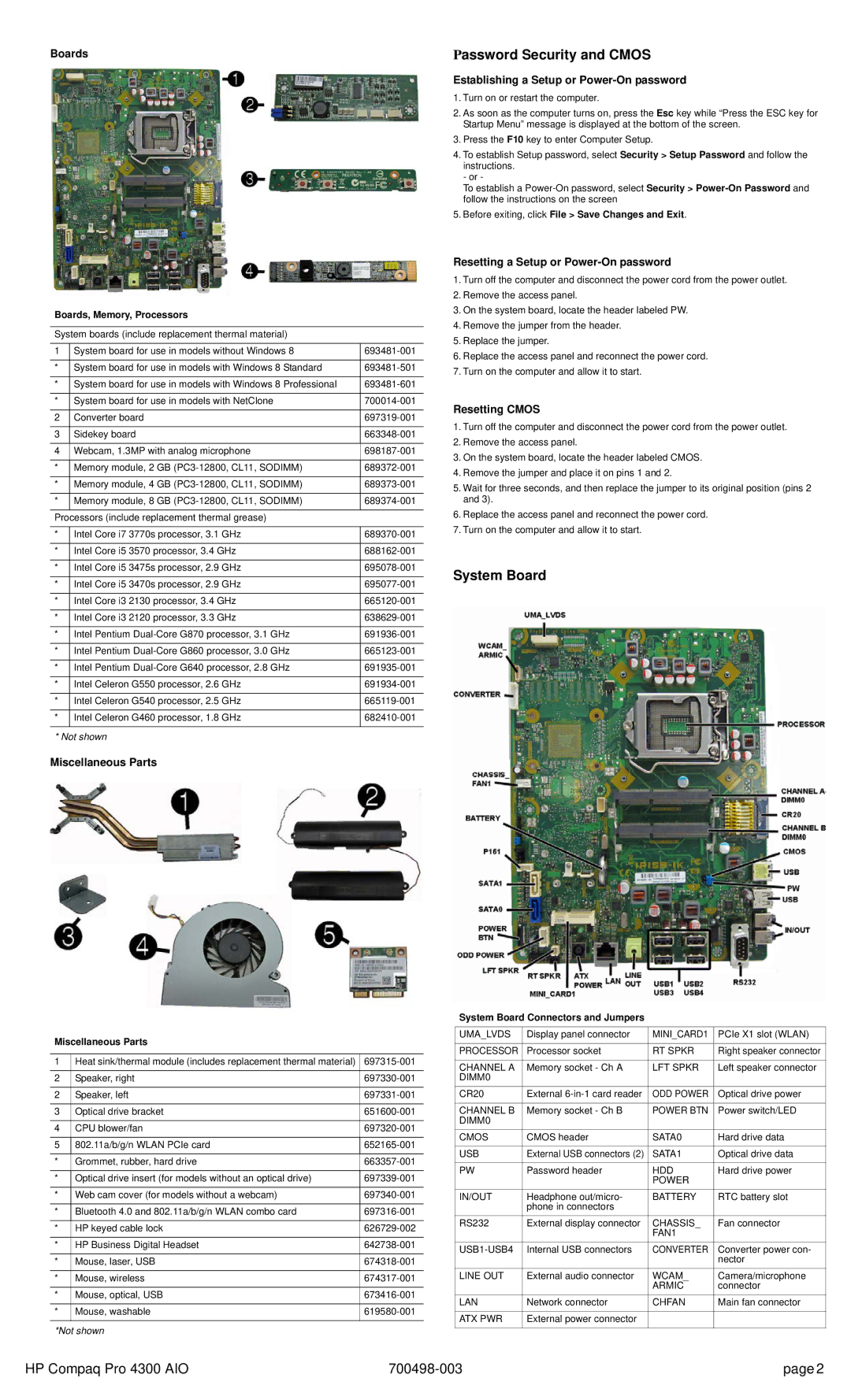
System Board
Miscellaneous Parts
1 | Heat sink/thermal module (includes replacement thermal material) | |
|
|
|
2 | Speaker, right | |
|
|
|
2 | Speaker, left | |
|
|
|
3 | Optical drive bracket | |
|
|
|
4 | CPU blower/fan | |
|
|
|
5 | 802.11a/b/g/n WLAN PCIe card | |
|
|
|
* | Grommet, rubber, hard drive | |
|
|
|
* | Optical drive insert (for models without an optical drive) | |
|
|
|
* | Web cam cover (for models without a webcam) | |
|
|
|
* | Bluetooth 4.0 and 802.11a/b/g/n WLAN combo card | |
|
|
|
* | HP keyed cable lock | |
|
|
|
* | HP Business Digital Headset | |
|
|
|
* | Mouse, laser, USB | |
|
|
|
* | Mouse, wireless | |
|
|
|
* | Mouse, optical, USB | |
|
|
|
* | Mouse, washable | |
|
|
|
*Not shown
System Board Connectors and Jumpers
UMA_LVDS | Display panel connector | MINI_CARD1 | PCIe X1 slot (WLAN) |
|
|
|
|
PROCESSOR | Processor socket | RT SPKR | Right speaker connector |
|
|
|
|
CHANNEL A | Memory socket - Ch A | LFT SPKR | Left speaker connector |
DIMM0 |
|
|
|
CR20 | External | ODD POWER | Optical drive power |
|
|
|
|
CHANNEL B | Memory socket - Ch B | POWER BTN | Power switch/LED |
DIMM0 |
|
|
|
CMOS | CMOS header | SATA0 | Hard drive data |
|
|
|
|
USB | External USB connectors (2) | SATA1 | Optical drive data |
|
|
|
|
PW | Password header | HDD | Hard drive power |
|
| POWER |
|
IN/OUT | Headphone out/micro- | BATTERY | RTC battery slot |
| phone in connectors |
|
|
RS232 | External display connector | CHASSIS_ | Fan connector |
|
| FAN1 |
|
Internal USB connectors | CONVERTER | Converter power con- | |
|
|
| nector |
LINE OUT | External audio connector | WCAM_ | Camera/microphone |
|
| ARMIC | connector |
LAN | Network connector | CHFAN | Main fan connector |
|
|
|
|
ATX PWR | External power connector |
|
|
|
|
|
|
HP Compaq Pro 4300 AIO | page 2 |