HP FireWire®/IEEE 1394a
PCIe x1 Card
Installation Guide
© Copyright 2010, 2012
Printed in
Second Edition: October 2012
*631518-B22*
Installing the 1394a PCIe x1 Card
1.Turn off power to the system and disconnect the power cord from the power outlet.
![]() WARNING! To avoid the risk of serious injury, ensure that the power cord is unplugged from the electrical outlet at the wall before installing the PCIe x1 card. Failure to do so may expose you to the risk of electric shock.
WARNING! To avoid the risk of serious injury, ensure that the power cord is unplugged from the electrical outlet at the wall before installing the PCIe x1 card. Failure to do so may expose you to the risk of electric shock.
![]() CAUTION: To avoid the risk of damage to the system, ensure that the power cord is unplugged from the electrical outlet at the wall before installing the PCIe x1 card.
CAUTION: To avoid the risk of damage to the system, ensure that the power cord is unplugged from the electrical outlet at the wall before installing the PCIe x1 card.
![]() NOTE: Refer to the documentation included with your computer for detailed information on installing an expansion card
NOTE: Refer to the documentation included with your computer for detailed information on installing an expansion card
2.Remove the computer cover or access panel.
3.Remove the appropriate expansion slot cover from the rear of the computer.
5.Insert the 1394a PCIe x1 card into an available PCIe 2.0 expansion slot in the computer.
![]() NOTE: The 1394a PCIe x1 card has a PCIe 2.0 5 GHz interface. For optimal performance, install this card in a PCIe 2.0 slot. Installing it in a PCIe 1.0 slot could cause the card to run at a reduced 2.5 GHz throughput. Refer to the documentation included with your computer for detailed instructions on installing an expansion card.
NOTE: The 1394a PCIe x1 card has a PCIe 2.0 5 GHz interface. For optimal performance, install this card in a PCIe 2.0 slot. Installing it in a PCIe 1.0 slot could cause the card to run at a reduced 2.5 GHz throughput. Refer to the documentation included with your computer for detailed instructions on installing an expansion card.
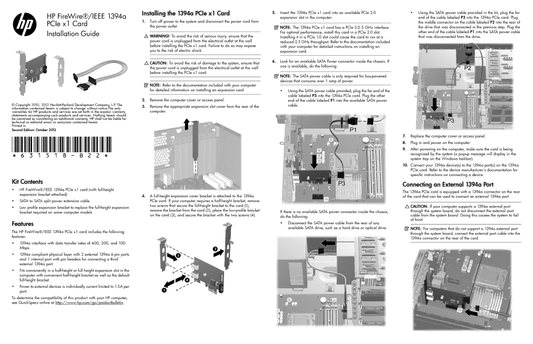
6.Look for an available SATA Power connector inside the chassis. If one is available, do the following:
![]() NOTE: The SATA power cable is only required for
NOTE: The SATA power cable is only required for
•Using the SATA power cable provided, plug the far end of the cable labeled P3 into the 1394a PCIe card. Plug the other end of the cable labeled P1 into the available SATA power cable.
•Using the SATA power cable provided in the kit, plug the far end of the cable labeled P3 into the 1394a PCIe card. Plug the middle connector on the cable labeled P2 into the rear of the drive that was disconnected in the previous step. Plug the other end of the cable labeled P1 into the SATA power cable that was disconnected from the drive.
7.Replace the computer cover or access panel.
8.Plug in and power on the computer.
9.After powering on the computer, make sure the card is being recognized by the system (a popup message will display in the system tray on the Windows taskbar).
10.Connect your 1394a device(s) to the 1394a port(s) on the 1394a PCIe card. Refer to the device manufacturer's documentation for specific instructions on connecting a device.
Kit Contents
•HP FireWire®/IEEE 1394a PCIe x1 card (with
•SATA to SATA split power extension cable
•Low profile expansion bracket to replace the
Features
The HP FireWire®/IEEE 1394a PCIe x1 card includes the following features:
•1394a interface with data transfer rates of 400, 200, and 100 Mbps.
•1394a compliant physical layer with 2 external 1394a
•Fits conveniently in a
•Power to external devices is individually current limited to 1.5A per port.
To determine the compatibility of this product with your HP computer, see QuickSpecs online at http://www.hp.com/go/productbulletin.
4.A
If there is no available SATA power connector inside the chassis, do the following:
•Disconnect the SATA power cable from the rear of any available SATA drive, such as a hard drive or optical drive.
Connecting an External 1394a Port
The 1394a PCIe card is equipped with a 1394a connector on the rear of the card that can be used to connect an external 1394a port.
![]() CAUTION: If your computer supports a 1394a external port through the system board, do not disconnect the external port cable from the system board. Doing this causes the system to fail at boot.
CAUTION: If your computer supports a 1394a external port through the system board, do not disconnect the external port cable from the system board. Doing this causes the system to fail at boot.
![]() NOTE: For computers that do not support a 1394a external port through the system board, connect the external port cable into the 1394a connector on the rear of the card.
NOTE: For computers that do not support a 1394a external port through the system board, connect the external port cable into the 1394a connector on the rear of the card.