INSTRUCTIONS
FOR
INSTALLATION, OPERATION and MAINTENANCE

 CHANCE TYPE M3 DISTRIBUTION SWITCH

GENERAL
▲! WARNING
Read and understand these instructions before installation or operation of this equipment. Competent personnel who understand proper safety procedures must select, install, and service this equipment. This instruction guide is written for such personnel. This guide is not a substitute for adequate training and experience in safety procedures for this type of equipment.
The A. B. Chance Type M3 disconnect switch is a
Select a properly rated M3 switch for each installation with consideration to continuous current, BIL, and rated voltage. Should there be any concern on the use of this M3 switch as rated, consult your supervisor before installation.
Inspect the switch for damage or missing parts. If damage from rough handling is evident, immediately file a claim with the transportation company. Contact the nearest Chance sales office for replacement parts.
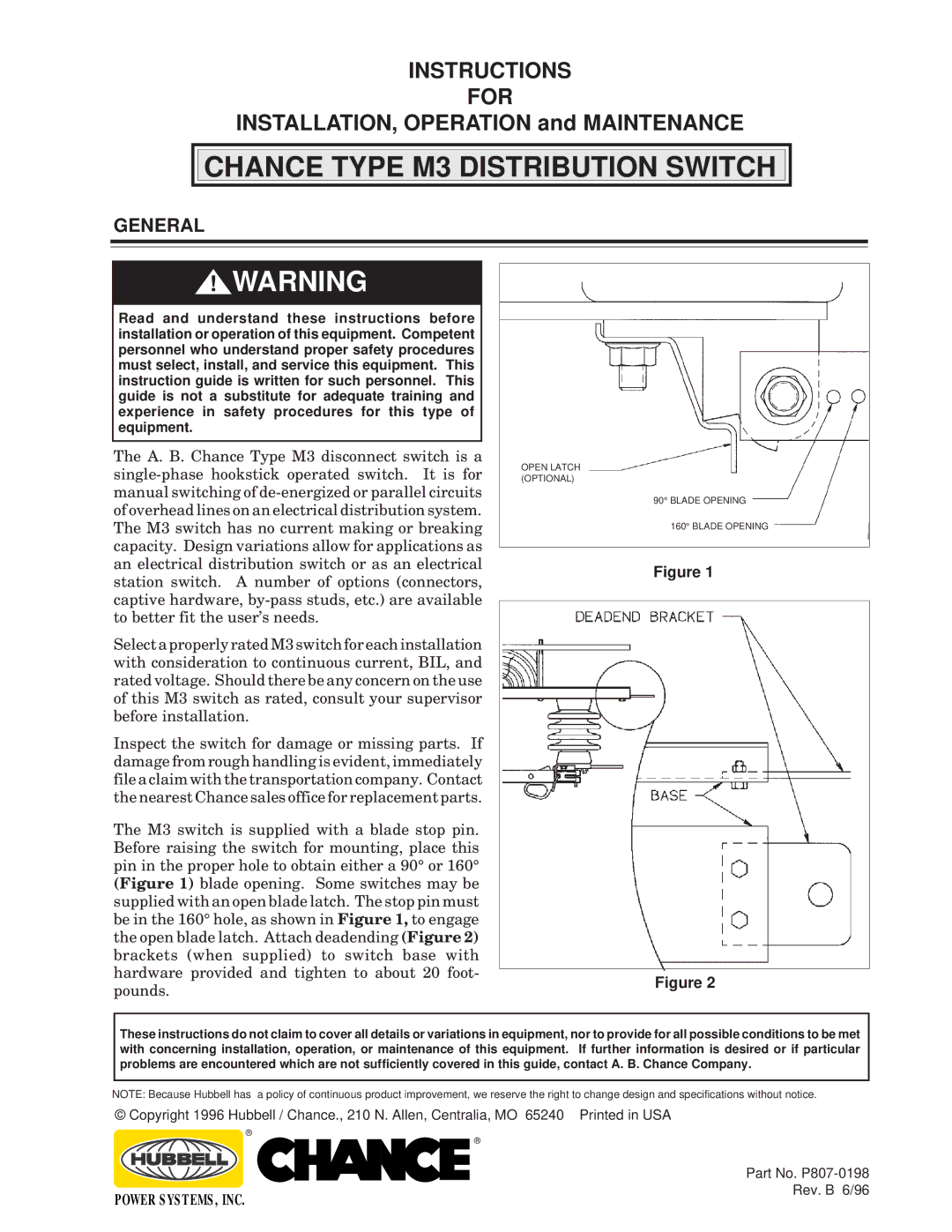
The M3 switch is supplied with a blade stop pin. Before raising the switch for mounting, place this pin in the proper hole to obtain either a 90° or 160° (Figure 1) blade opening. Some switches may be supplied with an open blade latch. The stop pin must be in the 160° hole, as shown in Figure 1, to engage the open blade latch. Attach deadending (Figure 2) brackets (when supplied) to switch base with hardware provided and tighten to about 20 foot- pounds.
OPEN LATCH (OPTIONAL)
90° BLADE OPENING
160° BLADE OPENING
Figure 1
Figure 2
These instructions do not claim to cover all details or variations in equipment, nor to provide for all possible conditions to be met with concerning installation, operation, or maintenance of this equipment. If further information is desired or if particular problems are encountered which are not sufficiently covered in this guide, contact A. B. Chance Company.
NOTE: Because Hubbell has a policy of continuous product improvement, we reserve the right to change design and specifications without notice.
© Copyright 1996 Hubbell / Chance., 210 N. Allen, Centralia, MO 65240 Printed in USA
®
®
|
|
|
| Part No. |
|
|
|
| |
|
|
|
| |
POWER SYSTEMS, INC. |
| Rev. B 6/96 | ||
|
| |||