CABLE REMOVAL
Use the following procedure to remove worn or damaged cable from reel prior to installation of new cable.
![]() CAUTION
CAUTION
Failure to relieve all spring tension prior to removing cable could result in damage to equipment or personal injury. Follow instructions carefully.
1.Move machine serviced by reel to a position closest to reel. Springs will still be under
2.Turn off all electric power.
3.Lock spool to prevent turning using either a spool lock mechanism or by tying off.
4.Disconnect cable from machine junction box.
5.Grip spool by hand and carefully release spool lock or tie. Slowly unwind remaining tension.
6.Again lock or tie spool to prevent rotation.
7.Remove cable from spool. Loosen
8.Install new cable following instruction at right.
CABLE INSTALLATION
Use the following procedure to replace cable or if reel was ordered without cable. Refer to CABLE INSTALLATION REFERENCE DRAWING, below.
1.Unspool new cable from shipping spool and lay out to eliminate twist.
NOTE: This step is not essential, but will aid in winding operation of the reel and prolong cable life.
2.Feed one end of the cable through
NOTE: This may require that jacket of cable be stripped to allow conductors to pass through shaft.
3.Connect individual conductors to appropriate rings on collector using crimp fitting or similar connection method.
4.Tighten
5.Wind the cable onto the reel spool by hand rotating spool in direction it turns free of spring tension.
6.Connect free end of cable to machine junction box.
7.Pretension reel and complete installation as previously described.
COLLECTOR REPLACEMENT
1.Turn off all power to reel.
2.Remove collector cover and gasket.
3.Disconnect electric leads to and from collector.
4.Remove drive stud bolt from bearing housing.
5.Remove button plug from hole in side of housing. Insert long 1/8” Allen wrench through hole and loosen two set screws in collector locking collar Set screws are at 90O
to one another..
NOTE: Older reels may have lock screws which must be removed to reach set screws holding collector to shaft.
6.Slide collector off shaft.
7.Install new collector by reversing above steps.
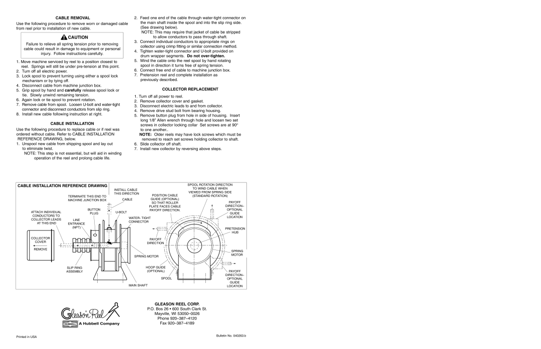
CABLE INSTALLATION REFERENCE DRAWING |
|
| SPOOL ROTATION DIRECTION | ||
|
| INSTALL CABLE |
| TO WIND CABLE WHEN | |
|
|
| VIEWED FROM SPRING SIDE | ||
|
| THIS DIRECTION | POSITION CABLE | ||
| TERMINATE THIS END TO | (STANDARD ROTATION) | |||
|
| ||||
| MACHINE JUNCTION BOX | CABLE | GUIDE (OPTIONAL) | PAYOFF | |
|
|
| SO THAT ROLLER | ||
| BUTTON |
| PLATE FACES CABLE | DIRECTION– | |
ATTACH INDIVIDUAL | PAYOFF DIRECTION. | OPTIONAL | |||
PLUG |
| GUIDE | |||
CONDUCTORS TO |
|
| |||
| WATER- TIGHT | LOCATION | |||
COLLECTOR LEADS | LINE | ||||
| |||||
CONNECTOR |
| ||||
AT THIS END | ENTRANCE |
| |||
|
|
| |||
| (NPT) |
|
| PRETENSION | |
|
|
|
| ||
|
|
|
| HUB | |
COLLECTOR |
|
| PAYOFF |
| |
COVER |
|
|
| ||
|
| DIRECTION |
| ||
|
|
|
| ||
REMOVE |
|
|
| SPRING | |
|
|
|
| ||
|
| SPRING MOTOR | MOTOR | ||
|
|
| |||
| SLIP RING |
| HOOP GUIDE |
| |
| ASSEMBLY |
| (OPTIONAL) | PAYOFF | |
|
|
| SPOOL | DIRECTION– | |
|
|
| OPTIONAL | ||
|
| MAIN SHAFT | GUIDE | ||
|
| LOCATION | |||
|
|
| GLEASON REEL CORP. | ||
| ® |
| P.O. Bos 26 • 600 South Clark St. | ||
|
| Mayville, WI | |||
|
|
| |||
| ® |
| Phone | ||
|
| Fax | |||
| HUBBELL A Hubbell Company | ||||
Printed in USA | Bulletin No. 040263.b |
|