Manuals
/
Huffy
/
Fitness & Sports
/
Fitness Equipment
Huffy
manual
Before You Start, 06/03, P/N 211972B
Models:
211972B
1
5
16
16
Download
16 pages
13.67 Kb
1
2
3
4
5
6
7
8
Install
Assembly
Elevator Height Adjustment
Number For Free Replacement
Safety
Page 5
Image 5
Page 4
Page 6
Page 5
Image 5
Page 4
Page 6
Contents
Have questions?...don’t go back to the store
Portable Basketball System with Elevator Owner’s Manual
SAFETY INSTRUCTIONS
NOTICE TO ASSEMBLERS
IN ANY WAY PRIOR TO OR AFTER ASSEMBLY, CALL TOLL-FREE
PARTS LIST - See Hardware Identifier
NUMBER FOR FREE REPLACEMENT
WARNING IF YOUR SYSTEM IS EQUIPPED WITH AN ACRYLIC
HARDWARE IDENTIFIER
Item #35 Item #31 Item #39 Item #43 Item #46 Item #53
HARDWARE IDENTIFIER continued
Item #37
Item #36
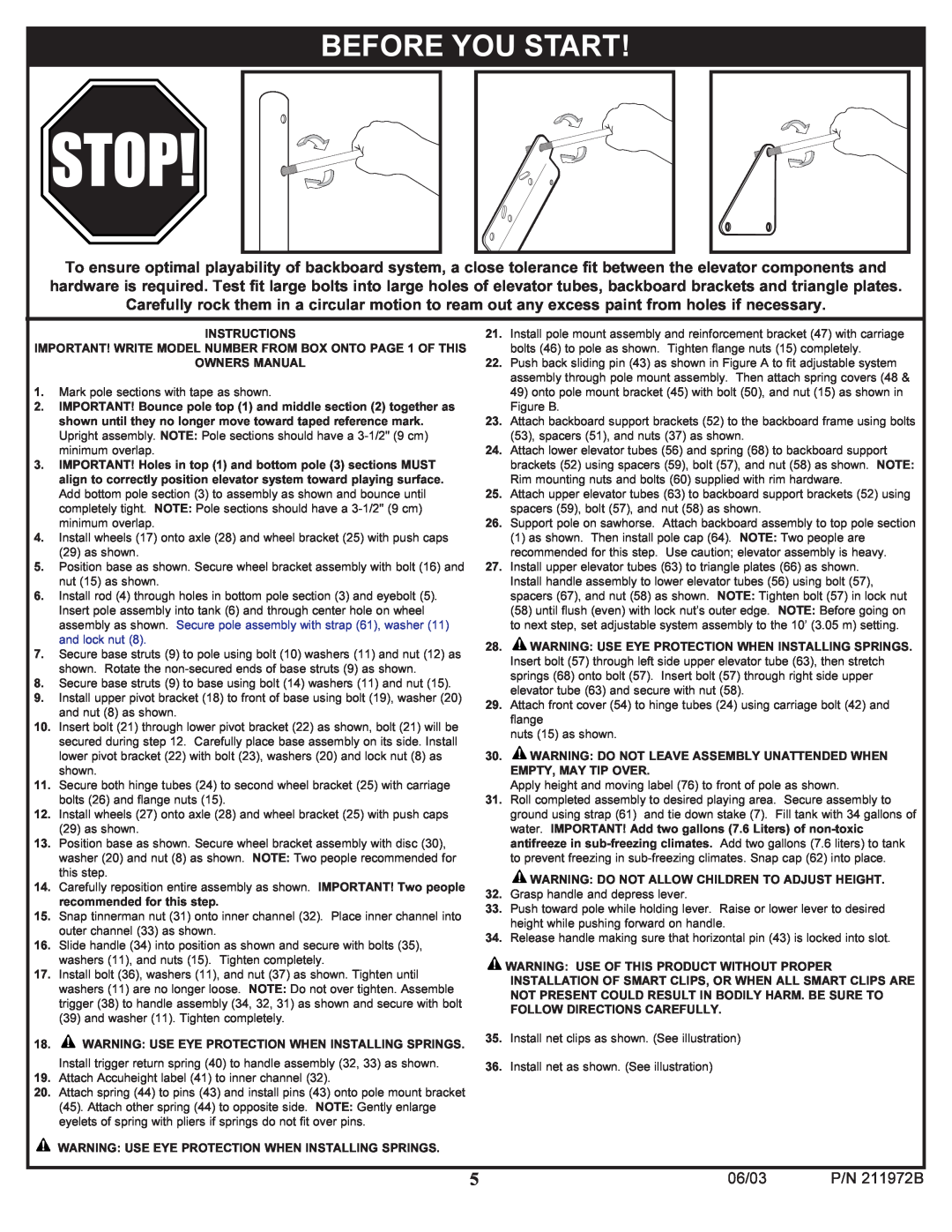
BEFORE YOU START
13 cm
MIDDLE
13 cm
BOTTOM
See Text Page
WITH LONGER
SIDE OF WHEEL
PLASTIC AXLE
NEEDS TO FACE THE
ELEVATOR INSTALLATION See steps
Fig. B
Fig. A
Refer To
Assembly
Instructions
Included With Rim
See Text Page
P/N 211972B
06/03
P/N 211972B
3.05m
ELEVATOR HEIGHT ADJUSTMENT
10 feet
CLIP “ARM” CLIP “BODY”
NET INSTALLATION
Top
Page
Image
Contents