www..reelscheSurfacemClutteratic..com
(Advanced)
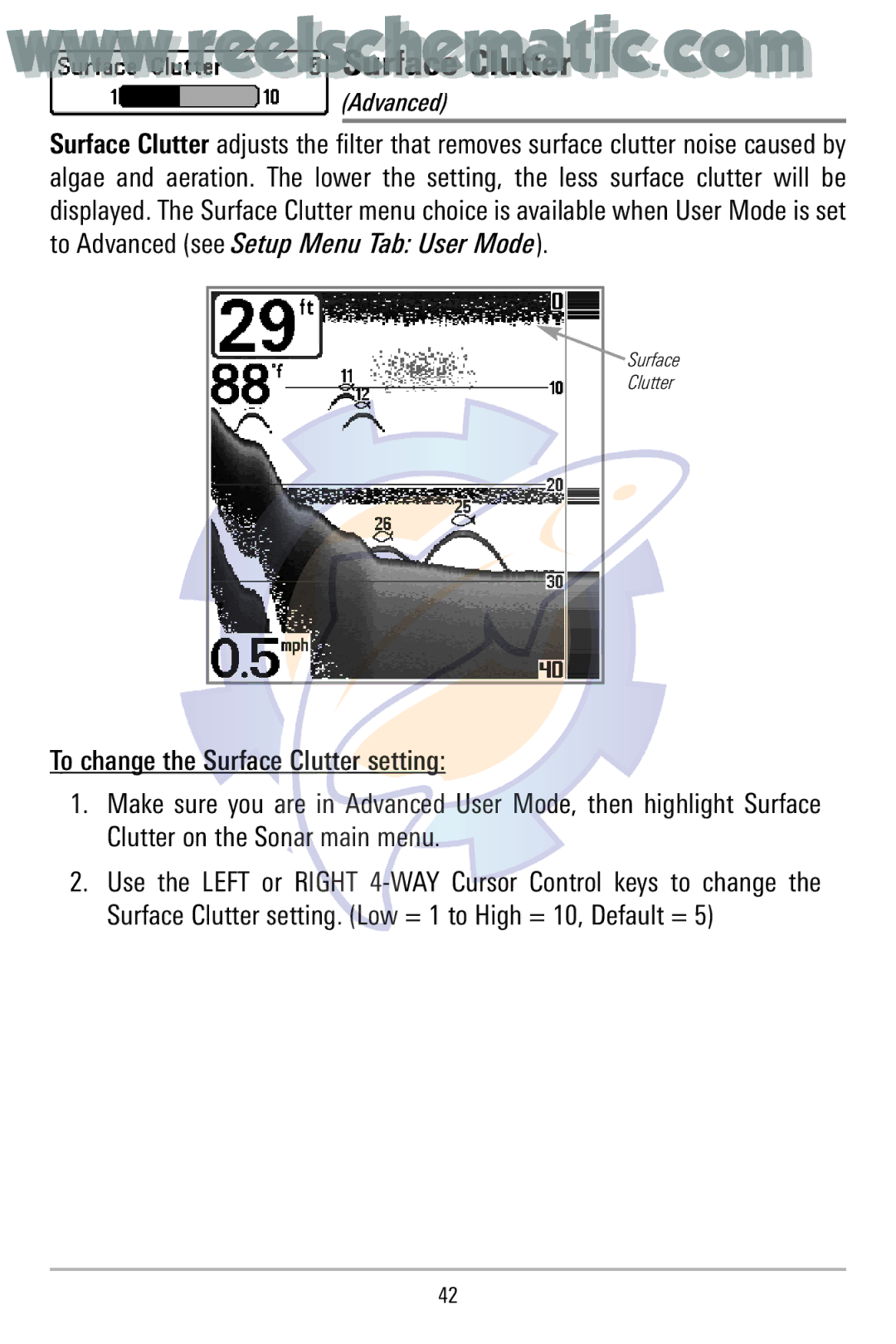
Surface Clutter adjusts the filter that removes surface clutter noise caused by algae and aeration. The lower the setting, the less surface clutter will be displayed. The Surface Clutter menu choice is available when User Mode is set to Advanced (see Setup Menu Tab: User Mode).
 Surface
Clutter
To change the Surface Clutter setting:
1.Make sure you are in Advanced User Mode, then highlight Surface Clutter on the Sonar main menu.
2.Use the LEFT or RIGHT
42