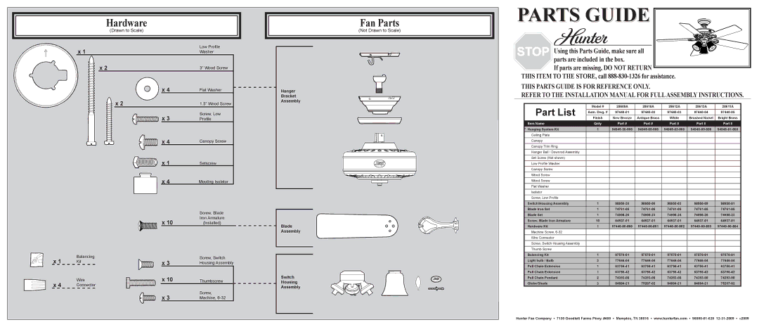
Hardware
(Drawn to Scale)
| x 1 |
| Low Profile |
|
| Washer | |
|
| x 2 | 3” Wood Screw |
|
| x 4 | Flat Washer |
|
| x 2 | 1.5” Wood Screw |
|
| x 3 | Screw, Low |
|
| Profile | |
|
| x 4 | Canopy Screw |
|
| x 1 | Setscrew |
|
| x 4 | Mouting Isolator |
|
|
| Screw, Blade |
|
| x 10 | Iron Armature |
|
| (Installed) | |
x 1 | Balancing |
| Screw, Switch |
Kit | x 3 | Housing Assembly | |
| |||
x 4 | Wire | x 10 | Thumbscrew |
Connector |
|
| |
|
| x 3 | Screw, |
|
| Machine, |
Fan Parts
(Not Drawn to Scale)
Hanger
Bracket
Assembly
Blade
Assembly
Switch
Housing
Assembly
PARTS GUIDE 


Using this Parts Guide, make sure all parts are included in the box.
If parts are missing, DO NOT RETURN ![]() THIS ITEM TO THE STORE, call
THIS ITEM TO THE STORE, call
THIS PARTS GUIDE IS FOR REFERENCE ONLY.
REFER TO THE INSTALLATION MANUAL FOR FULLASSEMBLY INSTRUCTIONS.
| Part List | Model # | 28609A | 28610A | 28612A | 28613A | 28611A |
| Asm. Dwg. # | ||||||
| Finish | New Bronze | Antique Brass | White | Brushed Nickel | Bright Brass | |
| Item Name | Qnty | Part # | Part # | Part # | Part # | Part # |
* Hanging System Kit | 1 | ||||||
| Ceiling Plate |
|
|
|
|
|
|
| Canopy |
|
|
|
|
|
|
|
|
|
|
|
|
|
|
| Canopy Trim Ring |
|
|
|
|
|
|
| Hanger Ball / Downrod Assembly |
|
|
|
|
|
|
|
|
|
|
|
|
|
|
| Set Screw (Not shown) |
|
|
|
|
|
|
| Low Profile Washer |
|
|
|
|
|
|
|
|
|
|
|
|
|
|
| Canopy Screw |
|
|
|
|
|
|
| Wood Screw |
|
|
|
|
|
|
| Wood Screw |
|
|
|
|
|
|
|
|
|
|
|
|
|
|
| Flat Washer |
|
|
|
|
|
|
| Isolator |
|
|
|
|
|
|
|
|
|
|
|
|
|
|
| Screw, Low Profile |
|
|
|
|
|
|
| Switch/Housing Assembly | 1 | |||||
| Blade Iron Set | 1 | |||||
| Blade Set | 1 | |||||
| Screw, Blade Iron Armature | 10 | |||||
| Hardware Kit | 1 | |||||
| Machine Screw, |
|
|
|
|
|
|
|
|
|
|
|
|
|
|
| Wire Connector |
|
|
|
|
|
|
| Screw, Switch Housing Assembly |
|
|
|
|
|
|
|
|
|
|
|
|
|
|
| Thumb Screw |
|
|
|
|
|
|
| Balancing Kit | 1 | |||||
| Light bulb / Bulb | 3 | |||||
| Pull Chain Extension | 1 | |||||
| Pull Chain Extension | 1 | |||||
| Pull Chain Pendant | 2 | |||||
| Globe/Shade | 3 | |||||
Hunter Fan Company • 7130 Goodlett Farms Pkwy. #400 • Memphis, TN 38016 • www.hunterfan.com •