HUNTER
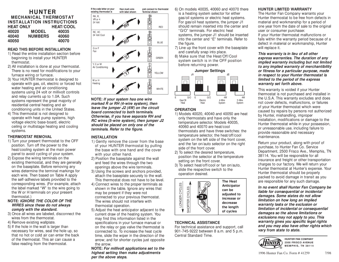
If the code letter on your | then mark wire | and connect to thermostat |
existing thermostat is | with label shown | Terminal shown |
6) On models 40035, 40060 and 40070 there |
is a heating system selector for either |
HUNTER LIMITED WARRANTY
The Hunter Fan Company warrants your
MECHANICAL THERMOSTAT INSTALLATION INSTRUCTIONS
HEAT ONLY | HEAT/COOL | |
40020 | MODEL | 40035 |
40040 | NUMBERS | 40060 |
40050 |
| 40070 |
READ THIS BEFORE INSTALLATION
1) | Read the entire installation section before |
| beginning to install your HUNTER |
| thermostat. |
2) | All installation is done at your thermostat. |
| There is no need for modifications to your |
| furnace wiring or furnace. |
3) | Your HUNTER thermostat is designed to |
| operate with gas, oil, electric or forced hot |
| water heating and air conditioning |
| systems using 24 volt or millivolt controls |
| and relay currents up to 1.0A. Such |
RH, R, VR or 4
24 Volt![]()
![]() RH
RH
RC, VC
24 Volt Cool ![]() RC
RC
G or F Fan
G
Y, C or M
Air Conditioning
Y
W or H
Heating
W
RH
RH
RED
RC
RC
BLUE
G
G
GREEN
Y
Y
YELLOW
W
W
WHITE
gas/oil systems or electric heat systems. |
For gas/oil heat systems, the jumper J1 |
should remain inserted into the center and |
“G/O” terminals. For electric heat |
systems, the jumper J1 should be inserted |
into the center and “E” terminals. Refer to |
the figure. |
7) Line up the front cover with the baseplate |
and carefully snap into place. |
8) Make sure that the Heat/Off/Cool |
system switch is in the OFF position |
before returning power. |
Jumper Settings
J1 |
|
|
|
|
|
|
|
|
|
| J2 |
|
|
|
|
|
|
|
|
|
|
|
|
|
|
|
|
|
|
|
|
|
|
|
|
|
|
|
|
|
|
|
|
|
|
|
|
|
|
|
|
|
|
|
|
|
|
|
|
Hunter thermostat to be free from defects in material and workmanship for a period of one year from the date of sale to the original user or consumer purchaser.
If your Hunter thermostat malfunctions or fails within the warranty period because of a defect in material or workmanship, Hunter will replace it.
This warranty is in lieu of all other express warranties. The duration of any implied warranty including but not limited to any implied warranty of merchantibility or fitness for a particular purpose, made in respect to your Hunter thermostat is limited to the period of the express warranty set forth above.
This warranty is voided if your Hunter thermostat is not purchased and installed in
systems represent the great majority of |
residential central heating and air |
conditioning units in the United States. |
4) This thermostat is not designed to |
operate with heat pump systems, high |
voltage electric |
ceiling or multistage heating and cooling |
systems. |
THERMOSTAT REMOVAL
1) Turn your present thermostat to the OFF |
position. Turn off the power to the |
heat/cooling system at the main power |
panel to avoid cycling of your system. |
2) Expose the wiring terminals on the |
existing thermostat, and they are generally |
on the baseplate. Before removing any |
wires determine the terminal markings for |
each wire. Then based on Table A apply |
the |
NOTE: If your system has one wire marked R or RH
INSTALLATION
1) Gently remove the cover from the base |
of your HUNTER thermostat by pulling |
the base with one hand and the cover |
with your other hand. |
2) Position the baseplate against the wall |
and feed the wires through the two |
openings above the wire terminals. |
3) Using the screws and anchors provided, |
attach the baseplate securely to the wall. |
This thermostat does not have to be level. |
E | G/O E | G/O | 4W | 4W |
Gas/Oil |
| Electric | ||
Heat |
| Heat | System | System |
OPERATION
1)Models 40020, 40040 and 40050 are heat only thermostats and have only the temperature selector. Models 40035, 40060 and 40070 are heat/cool thermostats and have three switches: the temperature selector, the heat/off/cool system on the left side of the front cover, and the fan on/auto selector on the right side of the front cover.
2)To select the desired temperature, position the selector at the temperature setting on the front cover.
3)To select heat/off/cool or fan on/auto, slide the respective switch to the operation desired.
the U.S.A. This warranty excludes and does not cover defects, malfunctions, or failures of your Hunter thermostat which were caused by repairs by persons not authorized by Hunter, mishandling, improper installation, modifications or damage to the Hunter thermostat while in your possession, or unreasonable use, including failure to provide reasonable and necessary maintenance.
Return your product, along with proof of purchase, to Hunter Fan Co. Service Department, 2500 Frisco Ave., Memphis, TN 38114. You will be responsible for all insurance and freight or other transportation charges to our factory. We will return your Hunter thermostat at Hunter’s expense. Your Hunter thermostat should be properly packed to avoid damage in transit as you
corresponding wires. (For example, attach |
the label marked “W” to the wire going to |
the W or H terminals on your present thermostat.)
NOTE: IGNORE THE COLOR OF THE WIRES since these do not always comply with the standard.
3) Once all wires are labeled, disconnect the |
wires from the thermostat. |
4) | Connect wires to the proper terminals as |
| shown in the table. Ignore any wires that |
| may be present if they were not |
| connected to your previous thermostat. |
| The wires should not interfere with |
| thermostat operation. |
5) | Adjust the heat anticipator adjacent to the |
| current draw of the heating system. You |
| may find this information listed in the |
LONGER CYCLES
SHORTER CYCLES
LONGER | .1 |
.2 |
|
.4 |
|
| 1.0 |
The Heat Anticipator can be adjusted to increase or decrease the length of cycles
are responsible for any such damage.
In no event shall Hunter Fan Company be liable for consequential or incidental damages. Some states do not allow limitation on how long an implied warranty lasts or the exclusion or limitation of incidental or consequential damages so the above limitations or exclusions may not apply to you. This
4) | Remove existing wallplate. |
5) | If the hole in the wall is larger than |
| necessary for wires, seal the hole up, so |
| that no hot or cold air can enter the back |
| of the thermostat. This air can cause a |
| false reading from the thermostat. |
specifications in your furnace manual or |
on the relay or gas valve the thermostat is |
connected to. To increase the heat cycle |
time, slide the wiper in the direction of the |
arrow; and for shorter cycles just opposite |
the arrow.
NOTE: For millivolt applications set to the highest setting then make adjustments per the above steps.
TECHNICAL ASSISTANCE
For technical assistance and support, call
warranty gives you specific legal rights and you may also have other rights which vary from state to state.
HUNTER FAN COMPANY 2500 FRISCO AVENUE MEMPHIS, TN 38114
®
1996 Hunter Fan Co. Form # 41259 | 7/98 |