42753-01 specifications
The Hunter Fan 42753-01 is a remarkable blend of style, efficiency, and modern technology, making it a standout choice for homeowners looking to enhance their living space with an effective ceiling fan. Renowned for its stylish design and powerful performance, the 42753-01 is an excellent addition to any room.One of the main features of the Hunter Fan 42753-01 is its impressive motor. The WhisperWind motor technology provides powerful airflow without the unpleasant noise often associated with traditional ceiling fans. This means you can enjoy a cool, comfortable environment without the distraction of a loud fan. The fan is designed to move a significant amount of air, ensuring that it effectively circulates throughout the room.
In addition to its performance, the Hunter Fan 42753-01 is also equipped with a variety of modern technologies that enhance its functionality. The fan includes a reversible motor, which allows users to change the direction of the blades. This feature is especially useful for seasonal use; in the summer months, the fan can rotate counter-clockwise to produce a cooling breeze, while in the winter months, reversing the direction helps circulate warm air that rises to the ceiling.
The design of the 42753-01 is another highlight. With its sleek lines and aesthetically pleasing finishes, it can seamlessly blend with various interior decor styles. The fan typically comes in several color options, allowing homeowners to choose one that best matches their existing decor. Additionally, the fan's blades are crafted from durable materials, ensuring longevity and stability.
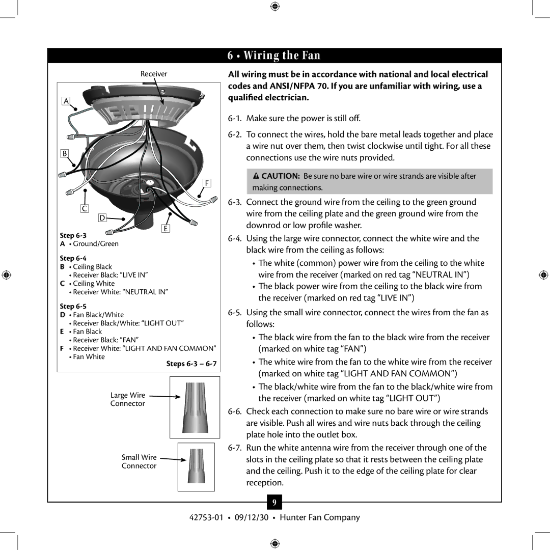
Installation is straightforward as well; the Hunter Fan 42753-01 is designed with user-friendliness in mind. It often comes with a well-detailed instruction manual, making it easy for anyone to install the fan without requiring professional assistance. Furthermore, many models in this range are compatible with Hunter's Universal Remote Control, allowing for effortless operation from anywhere in the room.
Finally, the Hunter Fan 42753-01 is also energy-efficient, typically designed to consume less power while still delivering robust airflow. This makes it an eco-friendly choice that can potentially lower energy bills throughout its lifetime. Overall, the Hunter Fan 42753-01 offers a perfect combination of aesthetics, technology, and efficiency, making it an ideal choice for enhancing home comfort.

