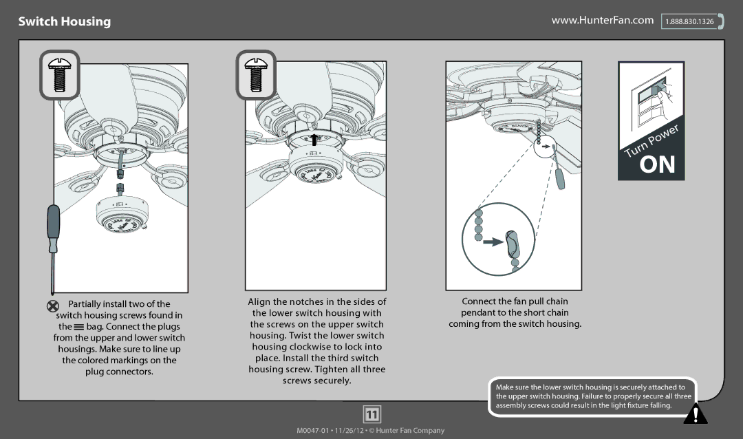
53071, 53075, 53082, 53081, 53080 specifications
The Hunter Fan Company has long been synonymous with quality and innovation in the ceiling fan industry. Five notable models from their range - the Hunter Fan 53086, 53080, 53078, 53081, and 53075 - exemplify the brand’s commitment to performance and style, making them excellent choices for enhancing the comfort of any indoor space.The Hunter Fan 53086, known for its sleek and contemporary design, features a whisper-quiet motor that ensures an undisturbed environment. Its integrated LED light kit offers bright illumination while being energy-efficient, allowing homeowners to save on electricity bills. The fan's three speed settings provide customizable airflow, making it perfect for any season.
Next, the Hunter Fan 53080 boasts a unique blend of rustic charm and modern technology. Its wooden blades are not only visually striking but are also designed for optimal air movement, ensuring a refreshing breeze throughout the room. The model includes a remote control for convenient adjustments from a distance and features a reversible motor that allows for year-round comfort by circulating warm air in the winter and cool air in the summer.
The Hunter Fan 53078 is a testament to classic design, featuring elegant blades and a rich finish that can complement various decor styles. This model is equipped with advanced airflow technology, allowing for more effective heating and cooling circulation. Its durable construction ensures longevity, while the easy-to-install mounting system simplifies the setup process.
The Hunter Fan 53081 offers a modern aesthetic with a minimalist profile. This model is perfect for smaller spaces, as its compact design does not compromise on airflow efficiency. The fan is compatible with smart home systems, allowing users to control it remotely through their smartphones, presenting a seamless integration of technology into everyday life.
Lastly, the Hunter Fan 53075 features an industrial design that appeals to modern sensibilities. This fan stands out with its robust motor and energy-saving capabilities, making it an eco-friendly option. Its LED light kit provides long-lasting illumination, reducing the need for frequent bulb replacements.
All these models showcase Hunter Fan's commitment to quality, performance, and innovative features. Their various designs cater to diverse tastes and preferences, ensuring that there is a Hunter fan for every home, promoting comfort and style effortlessly.

