ASSEMBLY
NOTE: Make sure unit is assembled cor- rectly as shown in this manual.
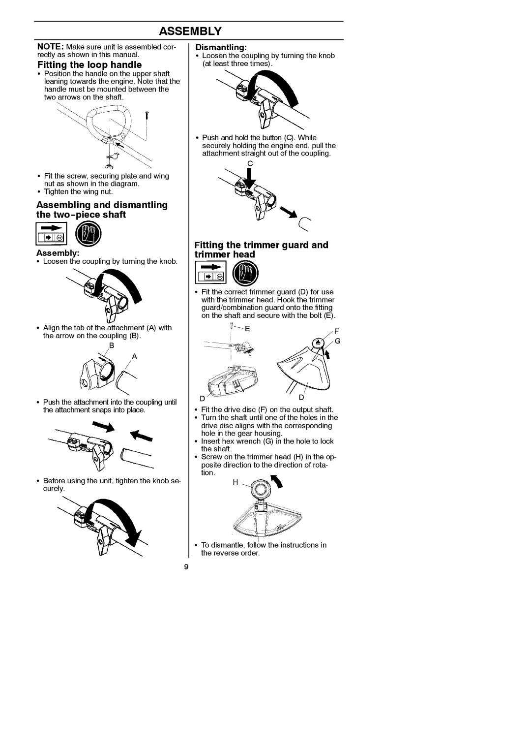
Fitting the loop handle
SPosition the handle on the upper shaft leaning towards the engine. Note that the handle must be mounted between the two arrows on the shaft.
SFit the screw, securing plate and wing nut as shown in the diagram.
STighten the wing nut.
Assembling and dismantling the two--piece shaft
Assembly:
SLoosen the coupling by turning the knob.
SAlign the tab of the attachment (A) with the arrow on the coupling (B).
B
![]() A
A
SPush the attachment into the coupling until the attachment snaps into place.
SBefore using the unit, tighten the knob se- curely.
9
Dismantling:
SLoosen the coupling by turning the knob (at least three times).
SPush and hold the button (C). While securely holding the engine end, pull the attachment straight out of the coupling.
C
Fitting the trimmer guard and trimmer head
SFit the correct trimmer guard (D) for use with the trimmer head. Hook the trimmer guard/combination guard onto the fitting on the shaft and secure with the bolt (E).

 EF G
EF G
DD
SFit the drive disc (F) on the output shaft. S Turn the shaft until one of the holes in the drive disc aligns with the corresponding
hole in the gear housing.
S Insert hex wrench (G) in the hole to lock the shaft.
S Screw on the trimmer head (H) in the op- posite direction to the direction of rota- tion.
H
STo dismantle, follow the instructions in the reverse order.