128LDX specifications
The Husqvarna 128LDX is a versatile and powerful string trimmer designed for homeowners and landscape enthusiasts alike. It boasts a range of features that make it an excellent choice for tackling various lawn care tasks, from trimming grass to cutting through tough weeds. With its lightweight and ergonomic design, the 128LDX provides exceptional maneuverability, allowing users to navigate around obstacles with ease.One of the standout features of the 128LDX is its powerful 28cc 2-stroke engine. This engine is designed to provide high performance while remaining fuel-efficient. The engine is easy to start, thanks to the incorporated Smart Start technology, which reduces the effort needed to pull the starter cord. This means users can spend less time wrestling with the trimmer and more time tending to their lawns.
The 128LDX also features Husqvarna's innovative LowVib system, which minimizes vibrations, significantly enhancing user comfort during prolonged use. This technology helps reduce fatigue, making it possible for users to work longer without discomfort. The trimmer is also designed with an adjustable handlebar, which further enhances comfort and control.
Equipped with a dual-line cutting system, the 128LDX makes quick work of overgrown areas. The Tap 'N Go feature allows users to easily feed more line while operating the trimmer, ensuring continued efficiency without interrupting the workflow. Additionally, the 128LDX's lightweight construction, at just over 10 pounds, means it's easy to carry and maneuver, reducing the strain on the user.
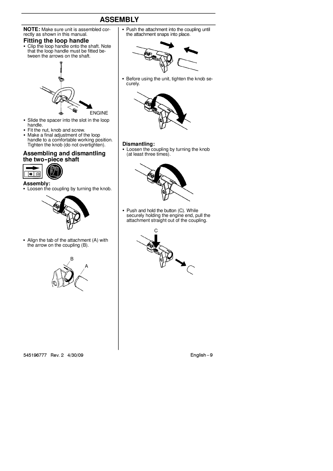
Another notable characteristic is the 128LDX's attachment capability. It is designed to be compatible with various Husqvarna attachments, allowing it to transform into other tools like a blower, edger, or cultivator. This versatility makes the 128LDX not just a string trimmer but a multi-functional tool that can address diverse gardening tasks.
In summary, the Husqvarna 128LDX is an excellent choice for homeowners seeking a reliable, versatile, and user-friendly string trimmer. Its combination of a powerful engine, innovative technologies, reduced vibrations, and multi-attachment capabilities make it a standout option for maintaining a beautiful yard. Whether it's trimming grass, tackling weeds, or performing various outdoor chores, the 128LDX ensures that users have the right tool for the job, making lawn care an efficient and enjoyable experience.

