ASSEMBLY
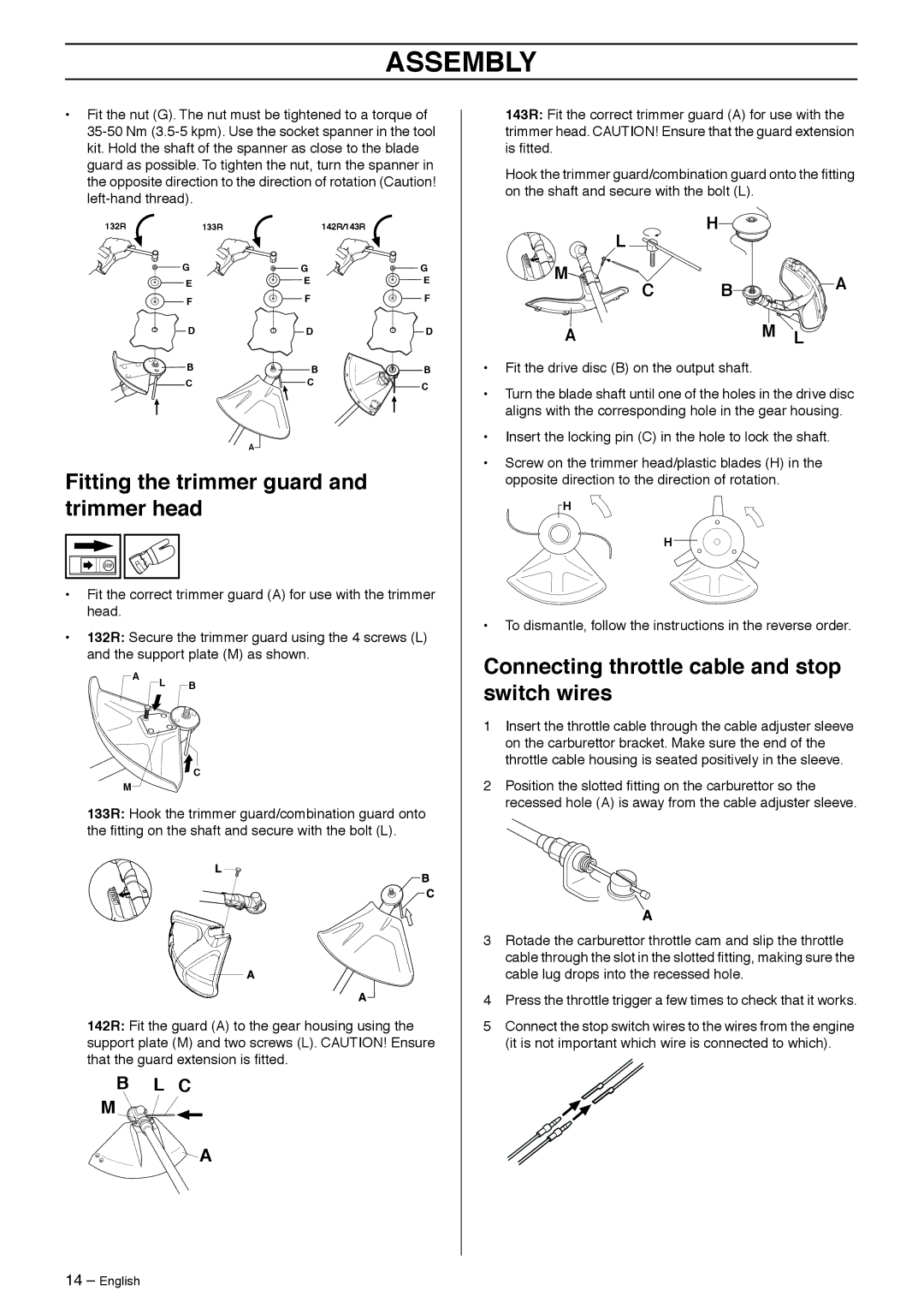
•Fit the nut (G). The nut must be tightened to a torque of
132R133R142R/143R
G | G | G |
E | E | E |
|
| |
F | F | F |
|
| |
D | D | D |
B | B | B |
C | C | C |
|
|
A![]()
Fitting the trimmer guard and trimmer head
• Fit the correct trimmer guard (A) for use with the trimmer head.
• 132R: Secure the trimmer guard using the 4 screws (L) and the support plate (M) as shown.
143R: Fit the correct trimmer guard (A) for use with the trimmer head. CAUTION! Ensure that the guard extension is fitted.
Hook the trimmer guard/combination guard onto the fitting on the shaft and secure with the bolt (L).
H![]()
![]()
L
M
C B![]()
![]()
![]() A
A
AM L
•Fit the drive disc (B) on the output shaft.
•Turn the blade shaft until one of the holes in the drive disc aligns with the corresponding hole in the gear housing.
•Insert the locking pin (C) in the hole to lock the shaft.
•Screw on the trimmer head/plastic blades (H) in the opposite direction to the direction of rotation.
![]() H
H
H
•To dismantle, follow the instructions in the reverse order.
Connecting throttle cable and stop
A
M
![]() L B
L B
![]() C
C
switch wires
1Insert the throttle cable through the cable adjuster sleeve on the carburettor bracket. Make sure the end of the throttle cable housing is seated positively in the sleeve.
2Position the slotted fitting on the carburettor so the recessed hole (A) is away from the cable adjuster sleeve.
133R: Hook the trimmer guard/combination guard onto the fitting on the shaft and secure with the bolt (L).
142R: Fit the guard (A) to the gear housing using the support plate (M) and two screws (L). CAUTION! Ensure that the guard extension is fitted.
BL C
M ![]()
![]()
![]()
![]()
A
3Rotade the carburettor throttle cam and slip the throttle cable through the slot in the slotted fitting, making sure the cable lug drops into the recessed hole.
4Press the throttle trigger a few times to check that it works.
5Connect the stop switch wires to the wires from the engine (it is not important which wire is connected to which).
14 – English
