335L, 335LS specifications
The Husqvarna 335LS is a versatile and robust string trimmer designed for both professional landscapers and avid gardeners. This machine combines power, efficiency, and user-friendly features, making it an ideal choice for tackling a variety of trimming tasks around the home or on larger job sites.One of the standout features of the Husqvarna 335LS is its powerful engine. Equipped with a 34.6cc, 2-stroke engine, it delivers high torque over a wide RPM range. This means that users can expect impressive performance while maintaining fuel efficiency, which is crucial for long working hours. The inclusion of the X-Torq technology not only enhances fuel efficiency but also reduces harmful emissions, aligning with today’s environmental standards.
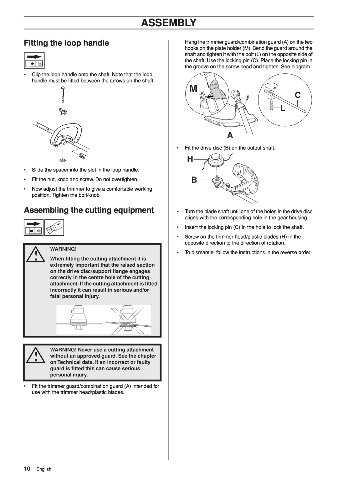
The cutting equipment on the 335LS is designed to handle different types of vegetation effortlessly. It comes with a Tap 'N Go trimmer head that allows for easy line feeding, ensuring continuous operation without interruptions. This feature is particularly beneficial when dealing with thick grass or weeds, as users can quickly extend the cutting line as needed.
Another significant characteristic of the Husqvarna 335LS is its lightweight design. Weighing just under 12 pounds, it is easy to maneuver without causing fatigue. The ergonomically designed handle provides a comfortable grip, which allows for extended use without discomfort. Additionally, the adjustable handle helps users find their ideal working position, further enhancing comfort and control.
The machine is also equipped with a smart start function, which reduces the resistance in the starter cord, allowing for easier ignition. This is particularly useful for users who may struggle with traditional starting systems, making the 335LS accessible to a wider audience.
Durability is another key aspect of the Husqvarna 335LS. It features high-quality materials and components designed to withstand the rigors of regular use. This reliability is further bolstered by features such as the heavy-duty gear head and sturdy construction.
In conclusion, the Husqvarna 335LS is designed with innovation and user-friendliness in mind. Its powerful engine, advanced technologies, lightweight design, and ease of use make it an excellent choice for anyone looking to maintain their lawn or complete landscaping tasks. Whether you are a professional or a homeowner, this string trimmer promises exceptional performance and long-lasting service.