REPAIR PARTS
TILLER - - MODEL NUMBER 700 DRT (96093000400), PRODUCT NUMBER 960 93
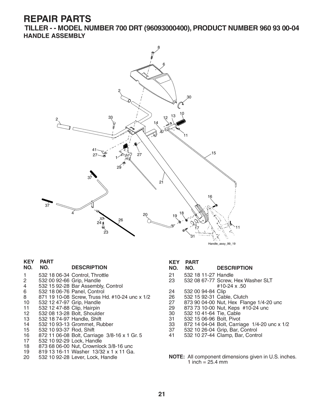
HANDLE ASSEMBLY
8
6
2
|
|
|
| 30 |
|
| 33 | 12 | 13 | 10 |
|
2 |
|
| |||
| 14 |
|
|
| |
|
|
|
|
| |
|
|
|
| 11 |
|
| 41 |
|
|
| 15 |
| 27 | 27 |
|
| |
|
|
|
| ||
|
| 1 |
|
|
|
|
| 29 |
|
|
|
| 37 | 21 |
|
|
|
|
|
|
|
| |
|
|
|
|
| 16 |
37 |
|
|
|
|
|
| 4 | 20 | 19 | 18 |
|
|
|
|
| ||
|
| 26 |
|
| |
| 24 |
|
|
| |
|
|
|
|
| |
| 23 |
|
| 17 | 11 |
|
|
| 31 |
| |
|
|
|
|
| |
|
|
|
|
| Handle_assy_99_19 |
KEY | PART |
| KEY | PART |
|
NO. | NO. | DESCRIPTION | NO. | NO. | DESCRIPTION |
1 | 532 18 | 21 | 532 18 | ||
2 | 532 00 | 23 | 532 08 | ||
4 | 532 15 |
|
| ||
6 | 532 18 | 24 | 532 00 | ||
8 | 871 19 | 26 | 532 15 | ||
10 | 532 12 | 27 | 873 90 | ||
11 | 532 12 | 29 | 873 73 | ||
12 | 532 08 | 30 | 532 10 | ||
13 | 532 18 | 31 | 532 15 | ||
14 | 532 10 | 33 | 872 14 | ||
15 | 532 10 | 37 | 532 10 | ||
16 | 872 11 | 41 | 532 10 | ||
17532 10
18873 68
19819 13
20 | 532 10 | NOTE: All component dimensions given in U.S. inches. |
|
| 1 inch = 25.4 mm |
21