SERVICE AND ADJUSTMENTS

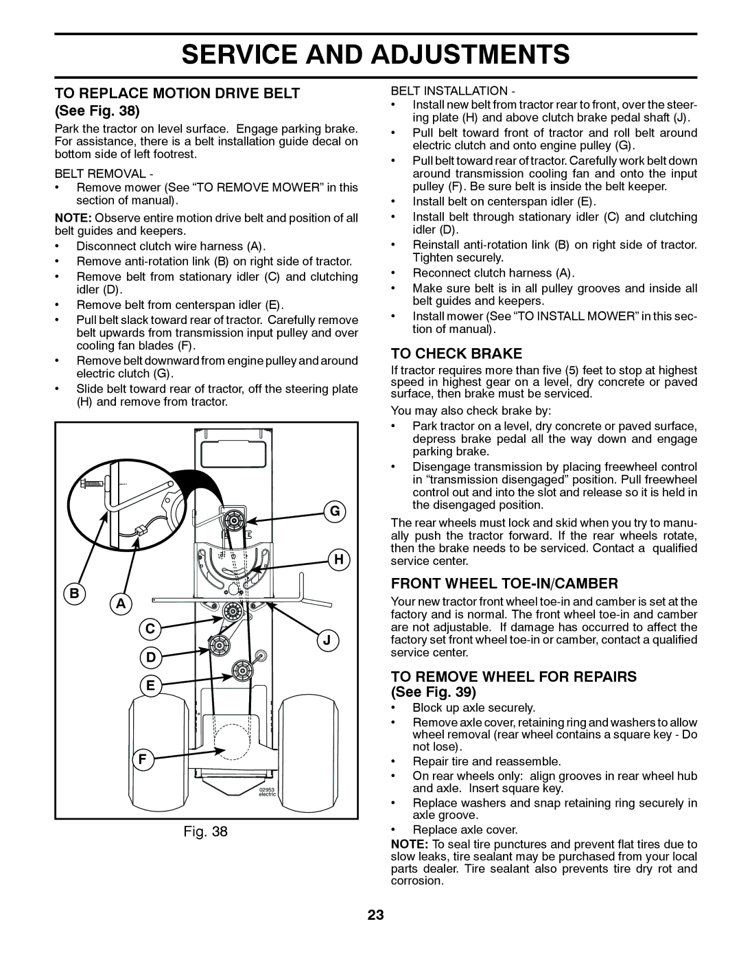
TO REPLACE MOTION DRIVE BELT (See Fig. 38)

Park the tractor on level surface. Engage parking brake. For assistance, there is a belt installation guide decal on bottom side of left footrest.

BELT REMOVAL -

Remove mower (See “TO REMOVE MOWER” in this section of manual).

NOTE: Observe entire motion drive belt and position of all belt guides and keepers.

Disconnect clutch wire harness (A).

Remove anti-rotation link (B) on right side of tractor.

Remove belt from stationary idler (C) and clutching idler (D).

Remove belt from centerspan idler (E).

Pull belt slack toward rear of tractor. Carefully remove belt upwards from transmission input pulley and over cooling fan blades (F).

Remove belt downward from engine pulley and around electric clutch (G).

Slide belt toward rear of tractor, off the steering plate

(H) and remove from tractor.


G


H

B

A


C

J


D


E


F


02953


electric

Fig. 38

BELT INSTALLATION -

Install new belt from tractor rear to front, over the steer- ing plate (H) and above clutch brake pedal shaft (J).

Pull belt toward front of tractor and roll belt around electric clutch and onto engine pulley (G).

Pull belt toward rear of tractor. Carefully work belt down around transmission cooling fan and onto the input pulley (F). Be sure belt is inside the belt keeper.

Install belt on centerspan idler (E).

Install belt through stationary idler (C) and clutching idler (D).

Reinstall anti-rotation link (B) on right side of tractor. Tighten securely.

Reconnect clutch harness (A).

Make sure belt is in all pulley grooves and inside all belt guides and keepers.

Install mower (See “TO INSTALL MOWER” in this sec- tion of manual).

TO CHECK BRAKE

If tractor requires more than five (5) feet to stop at highest speed in highest gear on a level, dry concrete or paved surface, then brake must be serviced.

You may also check brake by:

Park tractor on a level, dry concrete or paved surface, depress brake pedal all the way down and engage parking brake.

Disengage transmission by placing freewheel control in “transmission disengaged” position. Pull freewheel control out and into the slot and release so it is held in the disengaged position.

The rear wheels must lock and skid when you try to manu- ally push the tractor forward. If the rear wheels rotate, then the brake needs to be serviced. Contact a qualified service center.

FRONT WHEEL TOE-IN/CAMBER

Your new tractor front wheel toe-in and camber is set at the factory and is normal. The front wheel toe-in and camber are not adjustable. If damage has occurred to affect the factory set front wheel toe-in or camber, contact a qualified service center.

TO REMOVE WHEEL FOR REPAIRS (See Fig. 39)

Block up axle securely.

Remove axle cover, retaining ring and washers to allow wheel removal (rear wheel contains a square key - Do not lose).

Repair tire and reassemble.

On rear wheels only: align grooves in rear wheel hub and axle. Insert square key.

Replace washers and snap retaining ring securely in axle groove.

Replace axle cover.

NOTE: To seal tire punctures and prevent flat tires due to slow leaks, tire sealant may be purchased from your local parts dealer. Tire sealant also prevents tire dry rot and corrosion.

23

Page 23
Image 23
Husqvarna 532 43 65-03, 96045002202 To Replace Motion Drive Belt See Fig, To Check Brake, Front Wheel TOE-IN/CAMBER

532 43 65-03, 96045002202 specifications

The Husqvarna 532 43 65-03,96045002202 is a versatile and robust lawn mower blade designed to deliver exceptional cutting performance for a variety of mowing conditions. Known for its reliability and durability, this blade is an essential component for Husqvarna riding mowers and is a favored choice among homeowners and landscaping professionals.

One of the main features of the Husqvarna 532 43 65-03,96045002202 is its sharp cutting edge, made from high-quality steel designed to withstand the rigors of regular use. This blade is engineered to provide a clean and precise cut, promoting healthy grass growth and maintaining the aesthetic appeal of your lawn. Whether you're tackling thick grass, weeds, or uneven terrain, this blade's design ensures that your mower operates at optimal efficiency.

In terms of technology, this blade employs an innovative design that enhances airflow underneath the mower deck. This improved airflow leads to better grass lift and discharge, resulting in an even cut and reducing the chances of clumping. The efficient cutting performance also means that users can optimize their mowing time, making it ideal for those with larger lawns.

The Husqvarna 532 43 65-03,96045002202 is also designed with convenience in mind. Its dimensions and mounting design allow for easy installation and compatibility with a range of Husqvarna mower models. Users can enjoy a hassle-free experience when it comes to maintenance and blade replacement, increasing the overall productivity of their mowing tasks.

In addition to its cutting performance and ease of use, the durable construction of this blade means that it is less prone to wear and tear, providing long-lasting performance even in challenging environments. Customers appreciate the value for money that this blade offers, allowing them to get the most out of their lawn maintenance equipment without the need for frequent replacements.

Overall, the Husqvarna 532 43 65-03,96045002202 lawn mower blade stands out for its exceptional cutting capabilities, advanced design features, and user-friendly handling. Whether you are a homeowner looking to maintain an immaculate lawn or a professional gardener seeking reliable tools, this blade is an excellent choice that combines functionality with longevity.