English
Assembly
SWIVEL JOINT
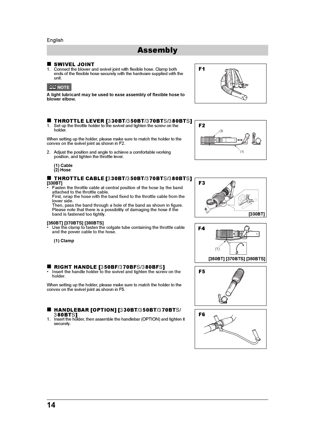
1.Connect the blower and swivel joint with flexible hose. Clamp both ends of the flexible hose securely with the hardware supplied with the unit.
![]() NOTE
NOTE
A light lubricant may be used to ease assembly of flexible hose to blower elbow.
F1
THROTTLE LEVER [330BT/350BT/370BTS/380BTS]
1.Set up the throttle holder to the swivel and tighten the screw on the holder.
When setting up the holder, please make sure to match the holder to the convex on the swivel joint as shown in F2.
2.Adjust the position and angle to achieve a comfortable working position, and tighten the throttle lever.
(1)Cable
(2)Hose
F2 |
(2) |
(1) |
THROTTLE CABLE [330BT/350BT/370BTS/380BTS]
[330BT]
• Fasten the throttle cable at central position of the hose by the band attached to the throttle cable.
First, wrap the hose with the band fixed to the throttle cable from the lower side.
Then, pass the band through a hole of the band as shown in figure. Please note that there is a possibility of damaging the hose if the band is fastened too tightly.
[350BT] [370BTS] [380BTS]
•Use the clamp to fasten the colgate tube containing the throttle cable and the power cable to the hose.
(1)Clamp
RIGHT HANDLE [350BF/370BFS/380BFS]
•Insert the handle holder to the swivel and tighten the screw on the holder.
When setting up the holder, please make sure to match the holder to the convex on the swivel joint as shown in F5.
HANDLEBAR [OPTION] [330BT/350BT/370BTS/ 80BTS]3
1.Insert the holder, then assemble the handlebar (OPTION) and tighten it securely.
F3 |
[330BT] |
F4 |
(1) |
[350BT] [370BTS] [380BTS] |
F5 |
F6 |
14
