SETUP AND ADJUSTMENTS
WARNING: No settings or adjustments are
to be made unless: Engine is stopped, key has been removed, park brake is on and battery cable removed from battery.
Setup
Uncrate machine.
Mount rear drive wheels using the lug nuts installed on the hubs.
Check the tire pressure in all four tires. All tires should be 15 psi.
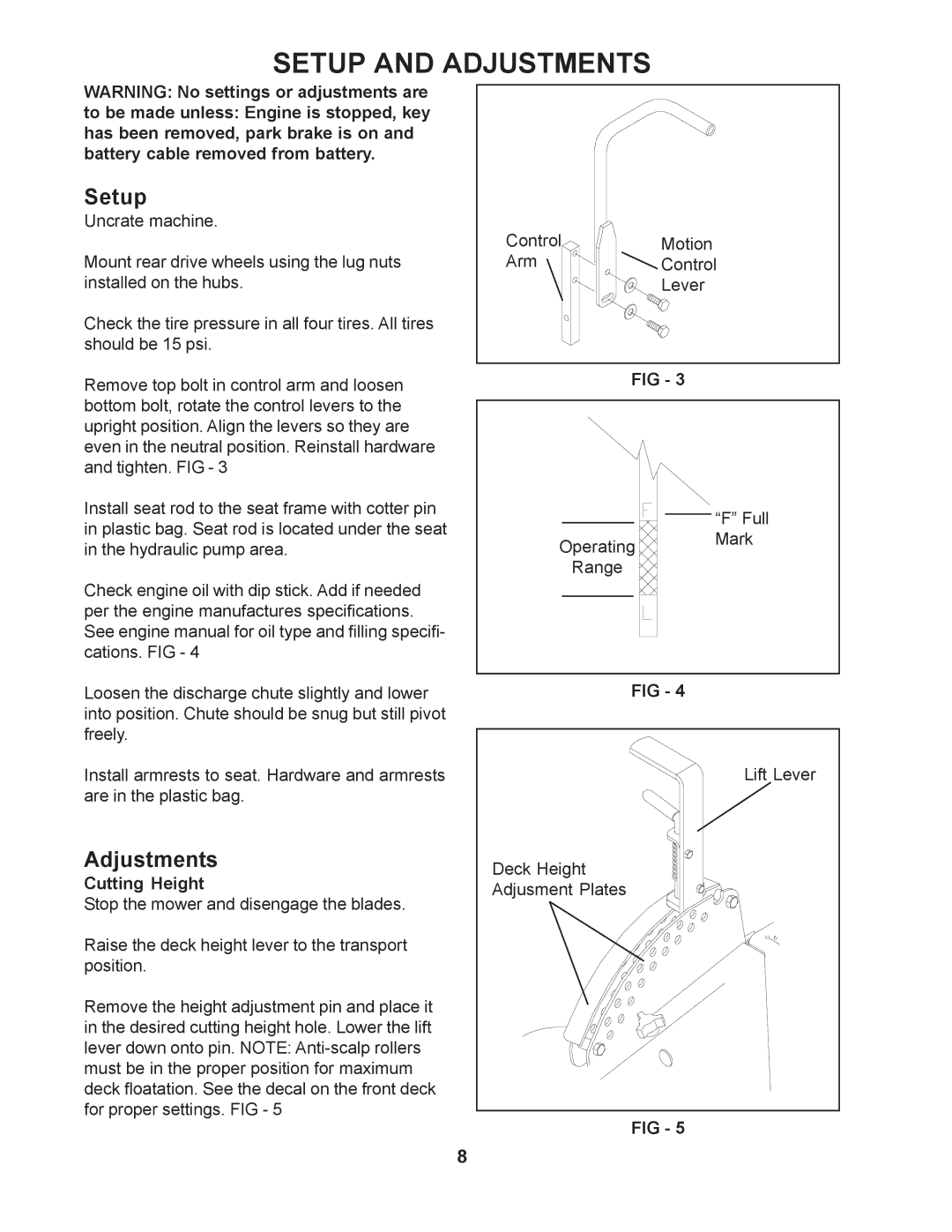
Remove top bolt in control arm and loosen bottom bolt, rotate the control levers to the upright position. Align the levers so they are even in the neutral position. Reinstall hardware and tighten. FIG - 3
Install seat rod to the seat frame with cotter pin in plastic bag. Seat rod is located under the seat in the hydraulic pump area.
Check engine oil with dip stick. Add if needed per the engine manufactures specifications. See engine manual for oil type and filling specifi- cations. FIG - 4
Loosen the discharge chute slightly and lower into position. Chute should be snug but still pivot freely.
Install armrests to seat. Hardware and armrests are in the plastic bag.
Adjustments
Cutting Height
Stop the mower and disengage the blades.
Raise the deck height lever to the transport position.
Remove the height adjustment pin and place it in the desired cutting height hole. Lower the lift lever down onto pin. NOTE:
Control | Motion |
Arm | Control |
| Lever |
FIG - 3
“F” Full
Operating Mark
Range
FIG - 4
Lift Lever
Deck Height
Adjusment Plates
FIG - 5
8