ASSEMBLY
TO INSTALL BAGGER COMPONENTS TO TRACTOR (See Figs. 4A-4D)
•Remove discharge chute from rear of tractor. Unhook the two (2) straps and pull chute out and away from tractor.
•Remove the two (2) 3/8 nuts and fl at washers from the bolts at the tractor back plate.
DISCHARGE
CHUTE
3/8 NUT ![]()
FLATWASHER
0 2277
FIG. 4A
•Using the nuts and fl at washers removed from tractor back plate, install the bagger support tube to the back plate as shown. Tighten securely.
SUPPORT
TUBE
FLAT
WASHER
3/8 NUT
BOLT | 02330 |
|
FIG. 4B
•Install the two upper support brackets through the back plate and to the chassis, install the clevis pin 10x17mm and secure with retainer spring.
•Assemble both support brackets to the outside of the baggger support tube install the clevis pin 10x50mm and secure with retainer spring.
•Replace discharge chute into rear opening of tractor. Secure the chute with the two hook straps.
CLEVIS PIN 10 X 17MM
CLEVIS PIN 10 X 50MM
SUPPORT BRACKET 13/32 FLAT WASHER
RETAINER SPRING
SUPPORT BRACKET
0 2813
FIG. 4C
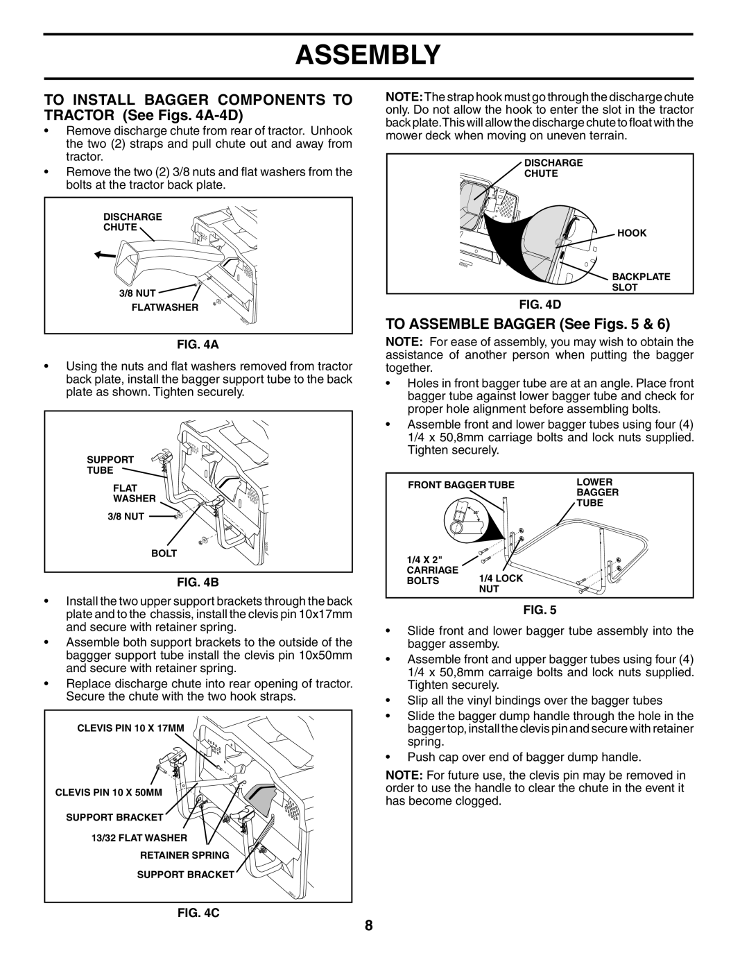
NOTE:The strap hook must go through the discharge chute only. Do not allow the hook to enter the slot in the tractor back plate.This will allow the discharge chute to float with the mower deck when moving on uneven terrain.
DISCHARGE
CHUTE
HOOK
02306
BACKPLATE
SLOT
FIG. 4D
TO ASSEMBLE BAGGER (See Figs. 5 & 6)
NOTE: For ease of assembly, you may wish to obtain the assistance of another person when putting the bagger together.
•Holes in front bagger tube are at an angle. Place front bagger tube against lower bagger tube and check for proper hole alignment before assembling bolts.
•Assemble front and lower bagger tubes using four (4) 1/4 x 50,8mm carriage bolts and lock nuts supplied. Tighten securely.
FRONT BAGGER TUBE | LOWER | ||
BAGGER | |||
|
| ||
|
| TUBE | |
1/4 X 2" |
|
| |
CARRIAGE | 1/4 LOCK |
| |
BOLTS | 2 | ||
0259 | |||
| NUT |
| |
FIG. 5
•Slide front and lower bagger tube assembly into the bagger assemby.
•Assemble front and upper bagger tubes using four (4) 1/4 x 50,8mm carraige bolts and lock nuts supplied. Tighten securely.
•Slip all the vinyl bindings over the bagger tubes
•Slide the bagger dump handle through the hole in the bagger top, install the clevis pin and secure with retainer spring.
•Push cap over end of bagger dump handle.
NOTE: For future use, the clevis pin may be removed in order to use the handle to clear the chute in the event it has become clogged.
8