IBM TotalStorage DS4400 Fibre Channel Cabling Instructions
Installing an IBM Small
The SFP module housing and fibre channel cable have integrated guide keys that prevent you from inserting these devices incorrectly. You must insert SFP modules into ports with minimal pressure so that you do not damage either the SFP module or the port. You can insert an SFP module into an active port without affecting the operational loop performance. You must connect the fibre channel cable to the SFP module after you insert the SFP module into the port.
Attention: To avoid damage to your
•Do not route the cable along a folding
•For devices on slide rails, leave enough slack in the cable so that it does not bend to a radius less than 38 mm (1.5 in.) when extended or become pinched when retracted.
•Route the cable away from places where it can be damaged by other devices in the rack cabinet.
•Do not use plastic cable ties in place of the provided cable straps.
•Do not overtighten the cable straps or bend the cables to a radius of less than 38 mm (1.5 in.).
•Do not put excess weight on the cable at the connection point. Be sure that the cable is well supported.
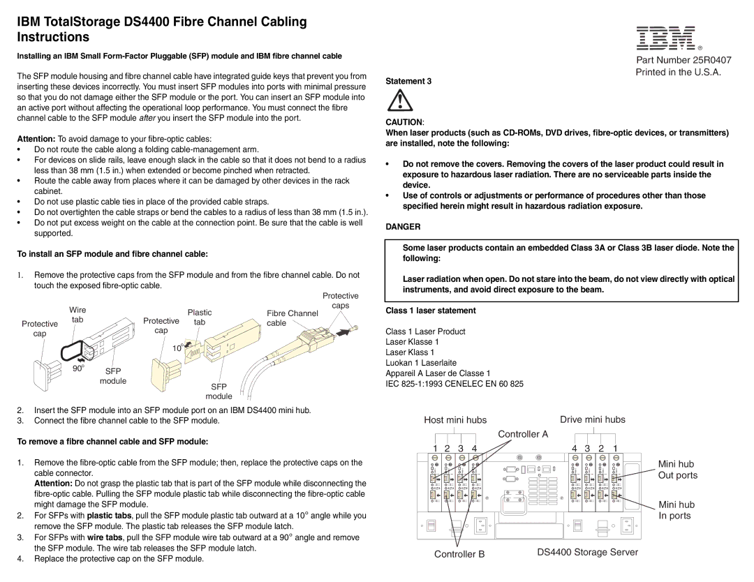
To install an SFP module and fibre channel cable:
1.Remove the protective caps from the SFP module and from the fibre channel cable. Do not touch the exposed
|
|
|
| Protective |
| Wire |
| Plastic | caps |
|
| Fibre Channel | ||
| tab | Protective | ||
Protective | tab | cable | ||
cap |
| cap |
|
|
|
|
|
|
®
Part Number 25R0407
Printed in the U.S.A.
Statement 3
CAUTION:
When laser products (such as
•Do not remove the covers. Removing the covers of the laser product could result in exposure to hazardous laser radiation. There are no serviceable parts inside the device.
•Use of controls or adjustments or performance of procedures other than those specified herein might result in hazardous radiation exposure.
DANGER
Some laser products contain an embedded Class 3A or Class 3B laser diode. Note the following:
Laser radiation when open. Do not stare into the beam, do not view directly with optical instruments, and avoid direct exposure to the beam.
Class 1 laser statement
Class 1 Laser Product
90o SFP module
10o![]()
![]()
![]()
![]()
![]()
SFP
module
Laser Klasse 1
Laser Klass 1 Luokan 1 Laserlaite Appareil A Laser de Classe 1
IEC
2.Insert the SFP module into an SFP module port on an IBM DS4400 mini hub.
3.Connect the fibre channel cable to the SFP module.
To remove a fibre channel cable and SFP module:
Host mini hubs | Drive mini hubs | ||||||||||
|
|
|
|
|
| Controller A |
|
|
|
|
|
|
|
|
|
|
|
|
|
|
| ||
|
|
|
|
|
|
|
|
|
|
|
|
1. | Remove the |
| cable connector. |
| Attention: Do not grasp the plastic tab that is part of the SFP module while disconnecting the |
| |
| might damage the SFP module. |
2. | For SFPs with plastic tabs, pull the SFP module plastic tab outward at a 10° angle while you |
| remove the SFP module. The plastic tab releases the SFP module latch. |
3. | For SFPs with wire tabs, pull the SFP module wire tab outward at a 90° angle and remove |
| the SFP module. The wire tab releases the SFP module latch. |
1 2 3 4
2G1b/sG b/s | ! | 2G1Gb/s | ! | 2Gb/s1 b/s | ! | 2G1b/sG b/s | ! |
| OUT |
| OUT |
| OUT |
| OUT |
| IN |
| IN |
| IN |
| IN |
4 | 3 |
| 2 |
| 1 | ||
2G1 Gb/s | ! | 2G1 Gb/s | ! | 2Gb/s1 b/s | ! | 2Gb/s1 b/s | ! |
| OUT |
| OUT |
| OUT |
| OUT |
| IN |
| IN |
| IN |
| IN |
Mini hub Out ports
Mini hub In ports
4. Replace the protective cap on the SFP module. |
Controller B | DS4400 Storage Server |