Image IMSG63120, IMSB63120, IMSB63120, IMSG63120 user manual

Models: IMSG63120, IMSB63120 IMSB63120, IMSG63120

1 20
Download 20 pages 49.87 Kb
Page 9
Image 9

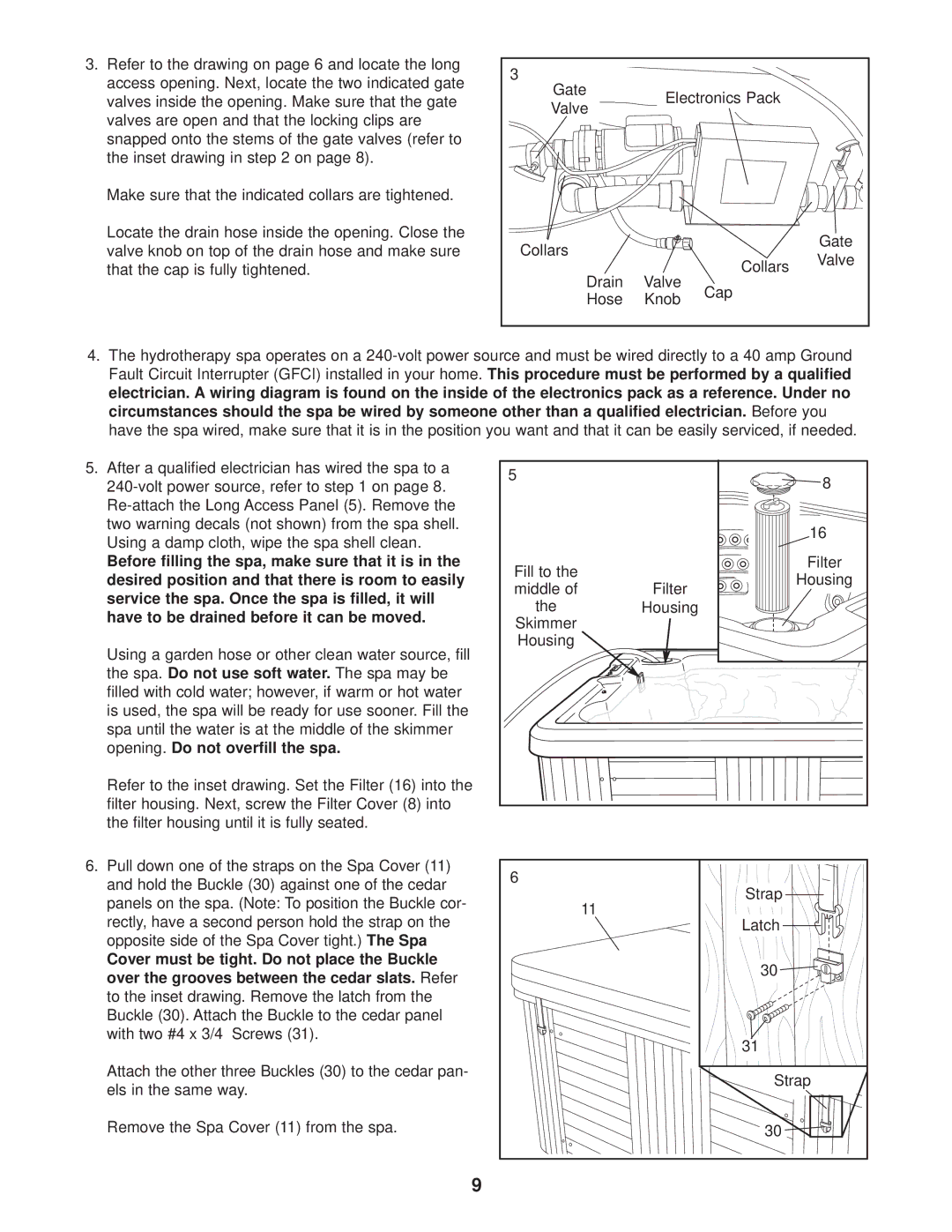
3.Refer to the drawing on page 6 and locate the long access opening. Next, locate the two indicated gate valves inside the opening. Make sure that the gate valves are open and that the locking clips are snapped onto the stems of the gate valves (refer to the inset drawing in step 2 on page 8).

Make sure that the indicated collars are tightened.

Locate the drain hose inside the opening. Close the valve knob on top of the drain hose and make sure that the cap is fully tightened.

3


Gate

Electronics Pack


Valve


Collars


Gate


Collars

Valve


Drain

Valve


Cap


Hose

Knob


4.The hydrotherapy spa operates on a 240-volt power source and must be wired directly to a 40 amp Ground Fault Circuit Interrupter (GFCI) installed in your home. This procedure must be performed by a qualified electrician. A wiring diagram is found on the inside of the electronics pack as a reference. Under no circumstances should the spa be wired by someone other than a qualified electrician. Before you have the spa wired, make sure that it is in the position you want and that it can be easily serviced, if needed.

5.After a qualified electrician has wired the spa to a 240-volt power source, refer to step 1 on page 8. Re-attach the Long Access Panel (5). Remove the two warning decals (not shown) from the spa shell. Using a damp cloth, wipe the spa shell clean.

Before filling the spa, make sure that it is in the desired position and that there is room to easily service the spa. Once the spa is filled, it will have to be drained before it can be moved.

Using a garden hose or other clean water source, fill the spa. Do not use soft water. The spa may be filled with cold water; however, if warm or hot water is used, the spa will be ready for use sooner. Fill the spa until the water is at the middle of the skimmer opening. Do not overfill the spa.

Refer to the inset drawing. Set the Filter (16) into the filter housing. Next, screw the Filter Cover (8) into the filter housing until it is fully seated.

6.Pull down one of the straps on the Spa Cover (11) and hold the Buckle (30) against one of the cedar panels on the spa. (Note: To position the Buckle cor- rectly, have a second person hold the strap on the opposite side of the Spa Cover tight.) The Spa

Cover must be tight. Do not place the Buckle over the grooves between the cedar slats. Refer to the inset drawing. Remove the latch from the Buckle (30). Attach the Buckle to the cedar panel with two #4 x 3/4” Screws (31).

Attach the other three Buckles (30) to the cedar pan- els in the same way.

Remove the Spa Cover (11) from the spa.

5


8


16

Fill to the


Filter

Filter

Housing

middle of


the

Housing


Skimmer


Housing


6


Strap


11


Latch


30


31


Strap


30

9

Page 9
Image 9
Image IMSG63120, IMSB63120, IMSB63120, IMSG63120 user manual

IMSG63120, IMSB63120, IMSB63120, IMSG63120 specifications

The Image IMSB63120 and IMSG63120 are highly regarded components in the modern imaging landscape, catering to a diverse range of applications in visual technology. These modules are distinguished by their state-of-the-art features, advanced technologies, and exceptional performance characteristics, making them key players in the industry.

At the core of the IMSB63120 and IMSG63120 modules is their cutting-edge imaging sensor technology. Both models utilize high-resolution image sensors that deliver remarkably clear and detailed images. These sensors offer superior low-light performance, allowing for high-quality image capture even in challenging lighting conditions. This capability makes them ideal for applications ranging from surveillance systems to automotive imaging.

Another notable feature of these models is their fast processing speed. Equipped with advanced image processing algorithms, they can handle complex imaging tasks swiftly and efficiently. This speed is further complemented by real-time processing capabilities, enabling the immediate transmission of image data without compromising quality. This technology is particularly beneficial in scenarios where timely decision-making is critical, such as in security and traffic monitoring systems.

Moreover, the IMSB63120 and IMSG63120 boast a broad dynamic range, which enhances their ability to capture fine details in both bright and dark areas of an image. This characteristic is essential for applications that require accurate color representation and detail capture, such as in medical imaging and broadcasting.

In terms of connectivity, both models offer a variety of interfaces, ensuring compatibility with numerous devices and systems. This flexibility allows for seamless integration into existing workflows, making them versatile options for both professionals and hobbyists alike.

To enhance user experience, the IMSB63120 and IMSG63120 include intuitive user interfaces that facilitate easy operation and customization. Users can adjust various settings according to the specific requirements of their projects, empowering them to achieve the best possible results.

In conclusion, the Image IMSB63120 and IMSG63120 are exemplary imaging solutions that combine high-resolution image capture with advanced processing capabilities. Their robust features, versatility, and performance make them essential tools in a myriad of imaging applications, ensuring they remain at the forefront of technology in their domain.