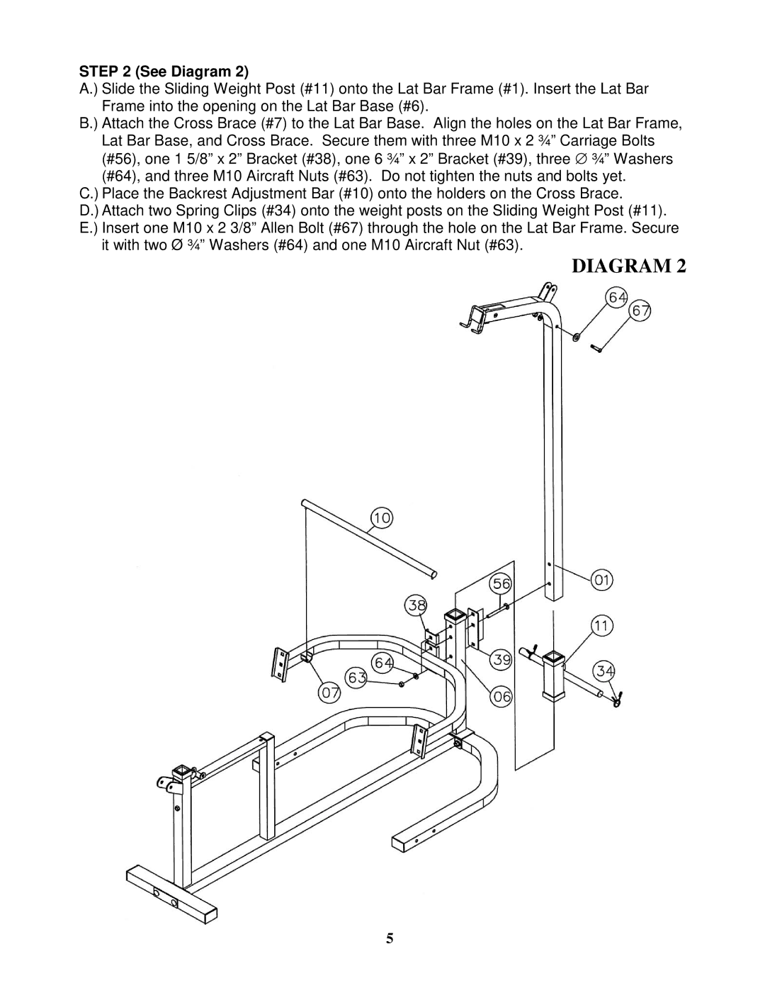
STEP 2 (See Diagram 2)
A.) Slide the Sliding Weight Post (#11) onto the Lat Bar Frame (#1). Insert the Lat Bar Frame into the opening on the Lat Bar Base (#6).
B.) Attach the Cross Brace (#7) to the Lat Bar Base. Align the holes on the Lat Bar Frame, Lat Bar Base, and Cross Brace. Secure them with three M10 x 2 ¾” Carriage Bolts (#56), one 1 5/8” x 2” Bracket (#38), one 6 ¾” x 2” Bracket (#39), three ∅ ¾” Washers (#64), and three M10 Aircraft Nuts (#63). Do not tighten the nuts and bolts yet.
C.) Place the Backrest Adjustment Bar (#10) onto the holders on the Cross Brace.
D.) Attach two Spring Clips (#34) onto the weight posts on the Sliding Weight Post (#11). E.) Insert one M10 x 2 3/8” Allen Bolt (#67) through the hole on the Lat Bar Frame. Secure
it with two Ø ¾” Washers (#64) and one M10 Aircraft Nut (#63).
DIAGRAM 2
5