ASSEMBLY INSTRUCTION
Tools Required Assembling the Machine: Two Adjustable Wrenches and Allen Wrenches.
NOTE: It is strongly recommended two or more people assembling this machine to avoid possible injury.
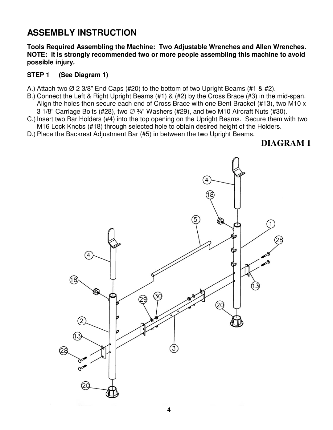
STEP 1 (See Diagram 1)
A.) Attach two Ø 2 3/8” End Caps (#20) to the bottom of two Upright Beams (#1 & #2).
B.) Connect the Left & Right Upright Beams (#1) & (#2) by the Cross Brace (#3) in the
C.) Insert two Bar Holders (#4) into the top opening on the Upright Beams. Secure them with two M16 Lock Knobs (#18) through selected hole to obtain desired height of the Holders.
D.) Place the Backrest Adjustment Bar (#5) in between the two Upright Beams.
DIAGRAM 1
4