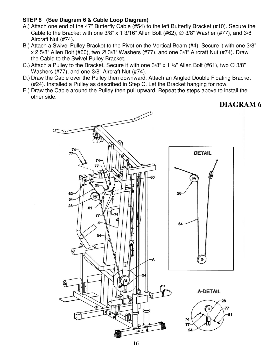
STEP 6 (See Diagram 6 & Cable Loop Diagram)
A.) Attach one end of the 47” Butterfly Cable (#54) to the left Butterfly Bracket (#10). Secure the Cable to the Bracket with one 3/8” x 1 3/16” Allen Bolt (#62), ∅ 3/8” Washer (#77), and 3/8” Aircraft Nut (#74).
B.) Attach a Swivel Pulley Bracket to the Pivot on the Vertical Beam (#4). Secure it with one 3/8” x 2 5/8” Allen Bolt (#60), two ∅ 3/8” Washers (#77), and one 3/8” Aircraft Nut (#74). Draw the Cable to the Swivel Pulley Bracket.
C.) Attach a Pulley to the Bracket. Secure it with one 3/8” x 1 ¾” Allen Bolt (#61), two ∅ 3/8” Washers (#77), and one 3/8” Aircraft Nut (#74).
D.) Draw the Cable over the Pulley then downward. Attach an Angled Double Floating Bracket (#24). Installed a Pulley as described in Step C. Let the Bracket hanging for now.
E.) Draw the Cable around the Pulley then pull upward. Repeat the steps above to install the other side.
DIAGRAM 6
16