STEP 2 (See Diagram 2)
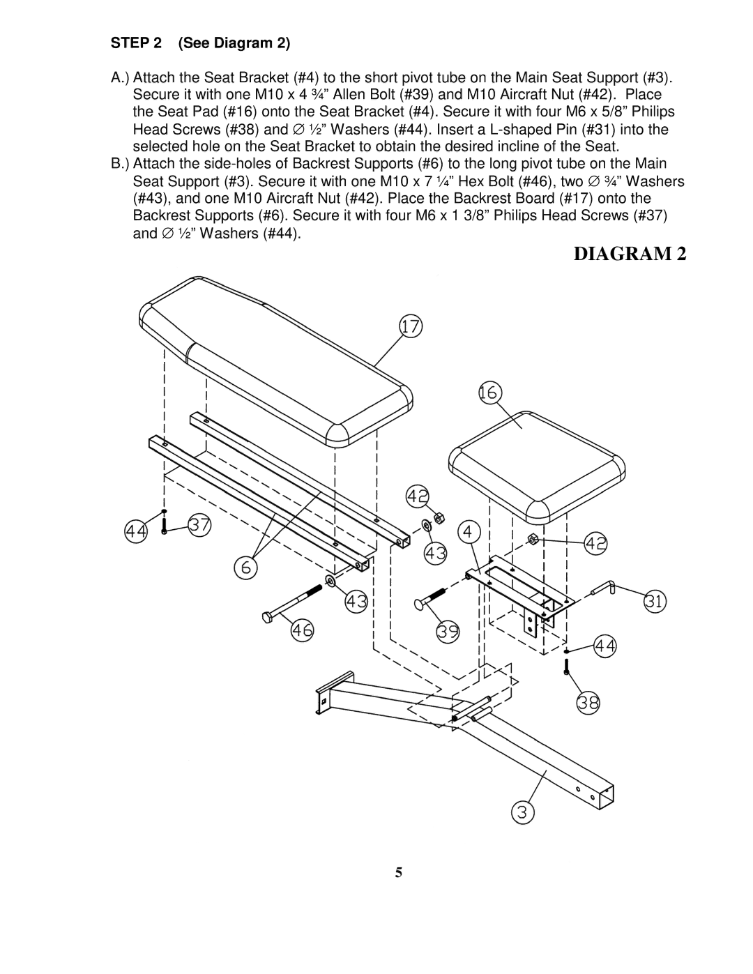
A.) Attach the Seat Bracket (#4) to the short pivot tube on the Main Seat Support (#3). Secure it with one M10 x 4 ¾” Allen Bolt (#39) and M10 Aircraft Nut (#42). Place the Seat Pad (#16) onto the Seat Bracket (#4). Secure it with four M6 x 5/8” Philips Head Screws (#38) and ∅ ½” Washers (#44). Insert a L-shaped Pin (#31) into the selected hole on the Seat Bracket to obtain the desired incline of the Seat.
B.) Attach the side-holes of Backrest Supports (#6) to the long pivot tube on the Main Seat Support (#3). Secure it with one M10 x 7 ¼” Hex Bolt (#46), two ∅ ¾” Washers (#43), and one M10 Aircraft Nut (#42). Place the Backrest Board (#17) onto the Backrest Supports (#6). Secure it with four M6 x 1 3/8” Philips Head Screws (#37) and ∅ ½” Washers (#44).
DIAGRAM 2
5