STEP 2 (See Diagram 2)
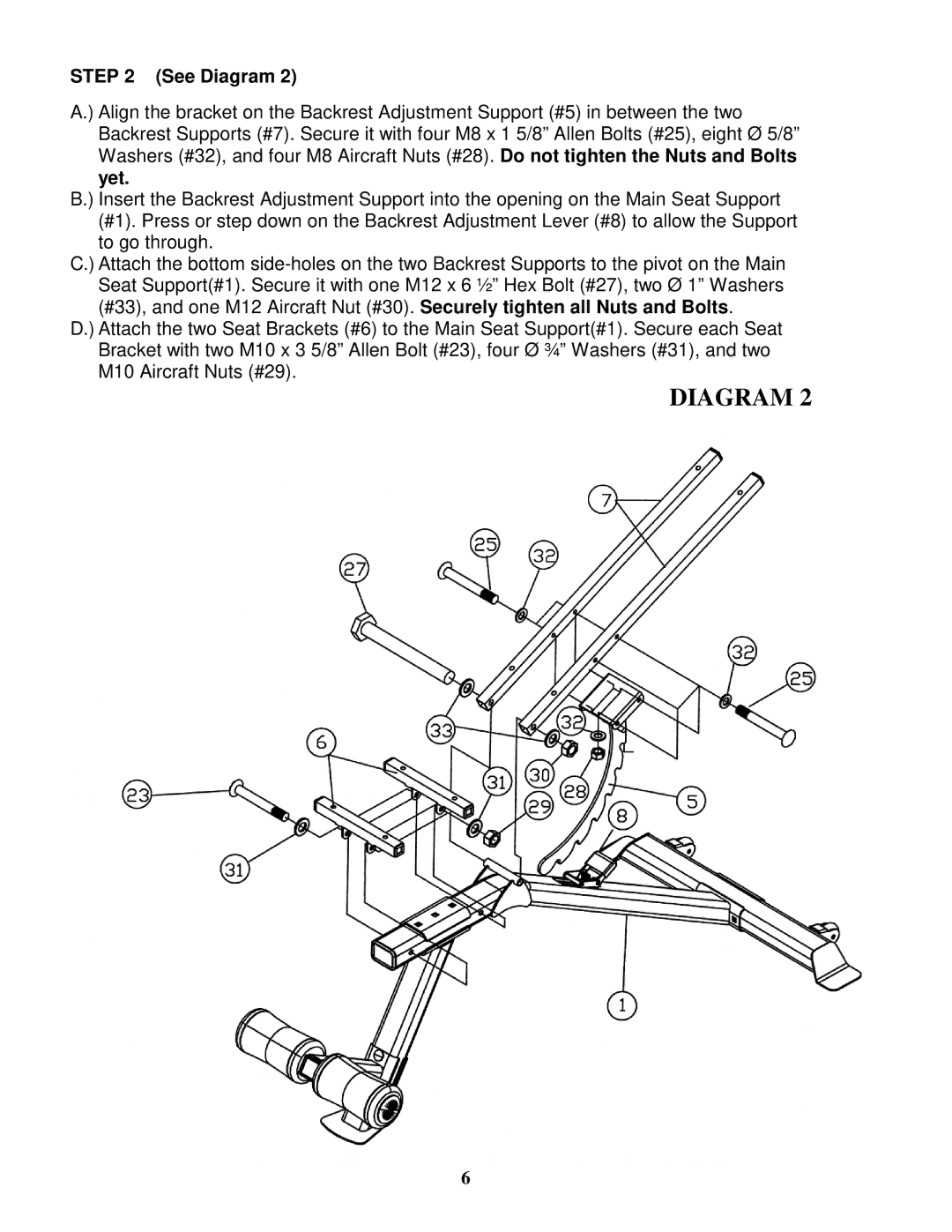
A.) Align the bracket on the Backrest Adjustment Support (#5) in between the two Backrest Supports (#7). Secure it with four M8 x 1 5/8” Allen Bolts (#25), eight Ø 5/8” Washers (#32), and four M8 Aircraft Nuts (#28). Do not tighten the Nuts and Bolts yet.
B.) Insert the Backrest Adjustment Support into the opening on the Main Seat Support (#1). Press or step down on the Backrest Adjustment Lever (#8) to allow the Support to go through.
C.) Attach the bottom
D.) Attach the two Seat Brackets (#6) to the Main Seat Support(#1). Secure each Seat Bracket with two M10 x 3 5/8” Allen Bolt (#23), four Ø ¾” Washers (#31), and two M10 Aircraft Nuts (#29).
DIAGRAM 2
6