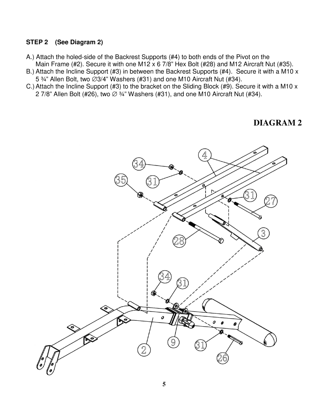
STEP 2 (See Diagram 2)
A.) Attach the
Main Frame (#2). Secure it with one M12 x 6 7/8” Hex Bolt (#28) and M12 Aircraft Nut (#35). B.) Attach the Incline Support (#3) in between the Backrest Supports (#4). Secure it with a M10 x
5 ¾” Allen Bolt, two ∅ 3/4” Washers (#31) and one M10 Aircraft Nut (#34).
C.) Attach the Incline Support (#3) to the bracket on the Sliding Block (#9). Secure it with a M10 x 2 7/8” Allen Bolt (#26), two ∅ ¾” Washers (#31), and one M10 Aircraft Nut (#34).
DIAGRAM 2
5