Instructions for the installer
Electrical connection
THE APPLIANCE MUST BE EARTHED
The hob is designed to work with alternating current at the supply voltage and frequency indicated on the rating plate (situated under the hob or at the end of the instruction booklet). Make sure that the local supply voltage corresponds to the voltage indicated on the rating plate.
Connecting the supply cable to the mains electricity supply
For models supplied without a plug, fit a standard plug, suitable for the load indicated on the rating plate, onto the cable and connect to a suitable socket.
To connect directly to the mains supply, a
•the limiter valve and the domestic system can withstand the load from the appliance (see rating plate);
•the supply system is efficiently earthed according to standards and laws in force;
•the socket or
Important: the wires in the mains lead are coloured in accordance with the following code:
Green & Yellow | - Earth |
Blue | - Neutral |
Brown | - Live |
As the colours of the wires in the mains lead may not correspond with the coloured markings identifying the terminals in your plug, proceed as follows:
Connect the Green & Yellow wire to terminal marked “E” or ![]() or coloured Green or Green & Yellow.
or coloured Green or Green & Yellow.
Connect the Brown wire to the terminal marked “L” or coloured Red.
Connect the Blue wire to the terminal marked “N” or coloured Black.
FAILURE TO OBSERVE THE
Replacing the cable
Use a rubber cable of the type
The
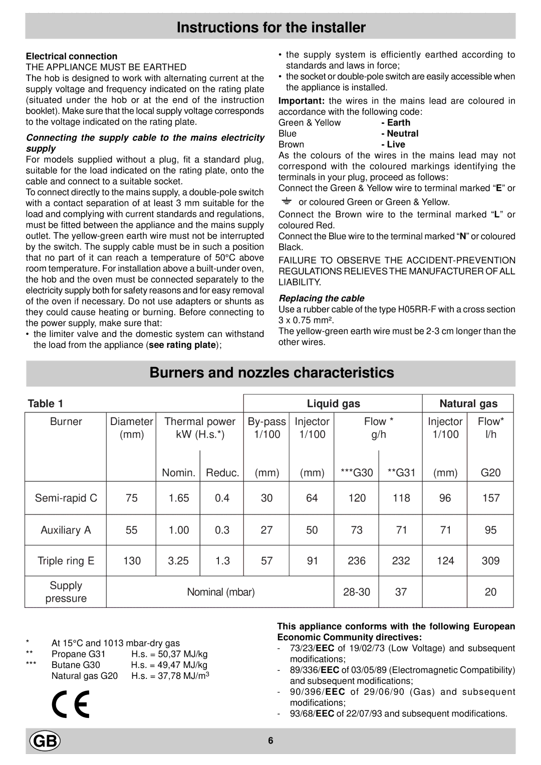
Burners and nozzles characteristics
Table 1 |
|
|
|
|
| Liquid gas |
| Natural gas | |||
|
|
|
|
|
|
|
|
|
| ||
Burner | Diameter | Thermal power | Injector | Flow * | Injector | Flow* | |||||
| (mm) | kW (H.s.*) | 1/100 | 1/100 | g/h |
| 1/100 | l/h | |||
|
| Nomin. |
| Reduc. | (mm) | (mm) | ***G30 |
| **G31 | (mm) | G20 |
|
|
|
| ||||||||
|
|
|
|
|
|
|
|
|
|
|
|
75 | 1.65 |
| 0.4 | 30 | 64 | 120 |
| 118 | 96 | 157 | |
|
|
|
|
|
|
|
|
|
|
|
|
Auxiliary A | 55 | 1.00 |
| 0.3 | 27 | 50 | 73 |
| 71 | 71 | 95 |
|
|
|
|
|
|
|
|
|
|
|
|
Triple ring E | 130 | 3.25 |
| 1.3 | 57 | 91 | 236 |
| 232 | 124 | 309 |
|
|
|
|
|
|
|
|
|
|
|
|
Supply |
| Nominal (mbar) |
|
| 37 |
| 20 | ||||
pressure |
|
|
|
| |||||||
|
|
|
|
|
|
|
|
|
|
| |
|
|
|
|
|
|
|
|
|
|
|
|
*At 15°C and 1013
** | Propane G31 | H.s. = 50,37 MJ/kg |
*** | Butane G30 | H.s. = 49,47 MJ/kg |
| Natural gas G20 | H.s. = 37,78 MJ/m3 |
This appliance conforms with the following European Economic Community directives:
-73/23/EEC of 19/02/73 (Low Voltage) and subsequent modifications;
-89/336/EEC of 03/05/89 (Electromagnetic Compatibility) and subsequent modifications;
-90/396/EEC of 29/06/90 (Gas) and subsequent modifications;
-93/68/EEC of 22/07/93 and subsequent modifications.
6