P R E C A U T I O N S A N D N O T E S
•The Kappa 54a has five levels of circuit protection that monitor the amplifier and will shut it down if the electrical system voltage drops below 10 Vdc or exceeds 15.5 Vdc, temperatures are above 194° F (90° C), short circuits occur, or current draw exceeds product specifications. For best performance, check the intended mounting site to make sure the operating environment does not create conditions that will trigger circuit protection.
•Prior to installation, turn off all audio systems and other electrical devices. Also disconnect the
•At the installation site, locate and make a note of all fuel lines, hydraulic brake lines, and electrical wiring. Use extreme caution when cutting or drilling in and around these areas.
•Use the amplifier as a mounting template to mark locations for the mounting holes.
•Check clearances on both sides of a planned mounting surface before drilling any holes or installing any screws. Remember that mounting screws can extend up to an inch behind the surface.
•Always wear protective eyewear when using tools.
•The Kappa 54a uses
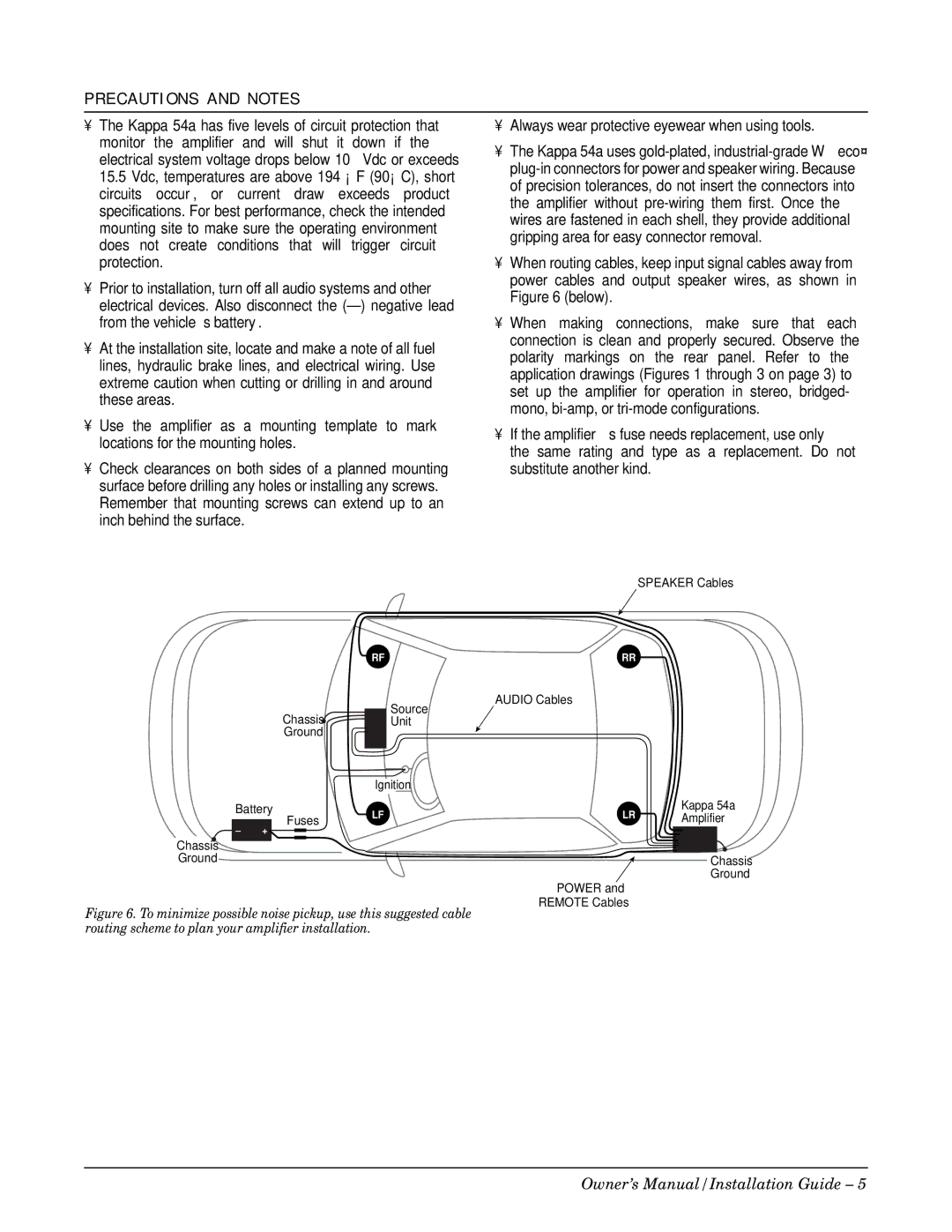
•When routing cables, keep input signal cables away from power cables and output speaker wires, as shown in Figure 6 (below).
•When making connections, make sure that each connection is clean and properly secured. Observe the polarity markings on the rear panel. Refer to the application drawings (Figures 1 through 3 on page 3) to set up the amplifier for operation in stereo, bridged- mono,
•If the amplifier’s fuse needs replacement, use only
the same rating and type as a replacement. Do not substitute another kind.
SPEAKER Cables
RF | RR |
Chassis ![]() Ground
Ground
Source Unit
AUDIO Cables
|
| Ignition |
|
|
Battery | LF | LR | Kappa 54a | |
– | Fuses | Amplifier | ||
+ |
|
|
| |
Chassis |
|
|
|
|
Ground |
|
|
| Chassis |
|
|
|
| Ground |
POWER and
REMOTE Cables
Figure 6. To minimize possible noise pickup, use this suggested cable routing scheme to plan your amplifier installation.
Owner’s Manual/Installation Guide – 5