BI-WIRING
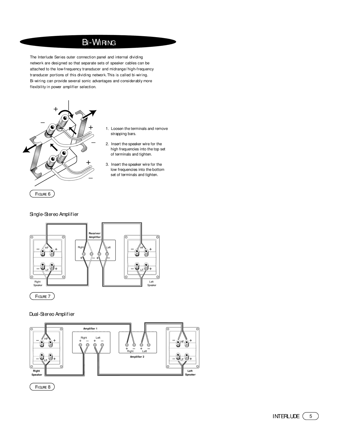
The Interlude Series outer connection panel and internal dividing network are designed so that separate sets of speaker cables can be attached to the
+
–
+
–
+
–
FIGURE 6
Single-Stereo Amplifier
1.Loosen the terminals and remove strapping bars.
2.Insert the speaker wire for the high frequencies into the top set of terminals and tighten.
3.Insert the speaker wire for the low frequencies into the bottom set of terminals and tighten.
Receiver/
Amplifier
– | HF | + | Right | Left | – | HF | + |
|
|
|
| ||||
|
|
| + | – + – |
|
|
|
– LF | + |
|
| – | LF + | ||
Right |
|
|
|
|
|
| Left |
Speaker |
|
|
|
|
|
| Speaker |
FIGURE 7
Amplifier 1
– | HF | + | Right | Left |
| – |
| + |
+ – | + – |
| HF | |||||
|
| |||||||
|
|
|
| + – | + – |
|
|
|
|
|
|
| Right | Left |
|
|
|
– LF | + |
| Amplifier 2 | – | LF | + | ||
|
|
| ||||||
Right |
|
|
|
|
|
|
| Left |
Speaker |
|
|
|
|
|
|
| Speaker |
FIGURE 8
INTERLUDE 5
