PARTS LIST / 651511-X

Item

Description (size)

Qty

Part No.

1

“O” Ring (1/16” x 5/16” o.d.)

(1)

Y325-8

2

Adjusting Screw (includes item 1)

(1)

65958

3

Cap

(1)

90995

4

“O” Ring (3/32” x 2-5/16” o.d.)

(1)

Y325-138

5

Piston Retainer

(1)

90555

6

Piston Washer

(1)

90586

7

Air Cylinder

(1)

90556

8

Piston

(1)

72842

9

Piston Washer

(1)

90559

10

Retaining Screw

(1)

90562

11

“O” Ring (1/16” x 3/8” o.d.)

(1)

Y325-10

12

“O” Ring (3/32” x 2-1/16” o.d.)

(1)

Y325-134

13

Air Cylinder

(1)

90994

14

Set Screw (1/4” - 20 x 5/16”)

(1)

Y29-43-C

15

Retainer

(1)

79255

16

Washer

(1)

F174-9

17

Packing

(3)

90565

18

Washer

(1)

F15-64

19

Spray Gun Body

(1)

92332

20

Screw (#8 - 36 x 1/4”)

(1)

Y191-82

21

Piston Rod

(1)

90732

22

Roll Pin (1/8” o.d. x 7/16”)

(1)

Y178-36

23

Ball and Socket Assembly

(1)

65774

24

Washer

(1)

72851

25

Valve Seat Assembly

(1)

65853

26

Washer

(1)

75815

DISASSEMBLY / REASSEMBLY

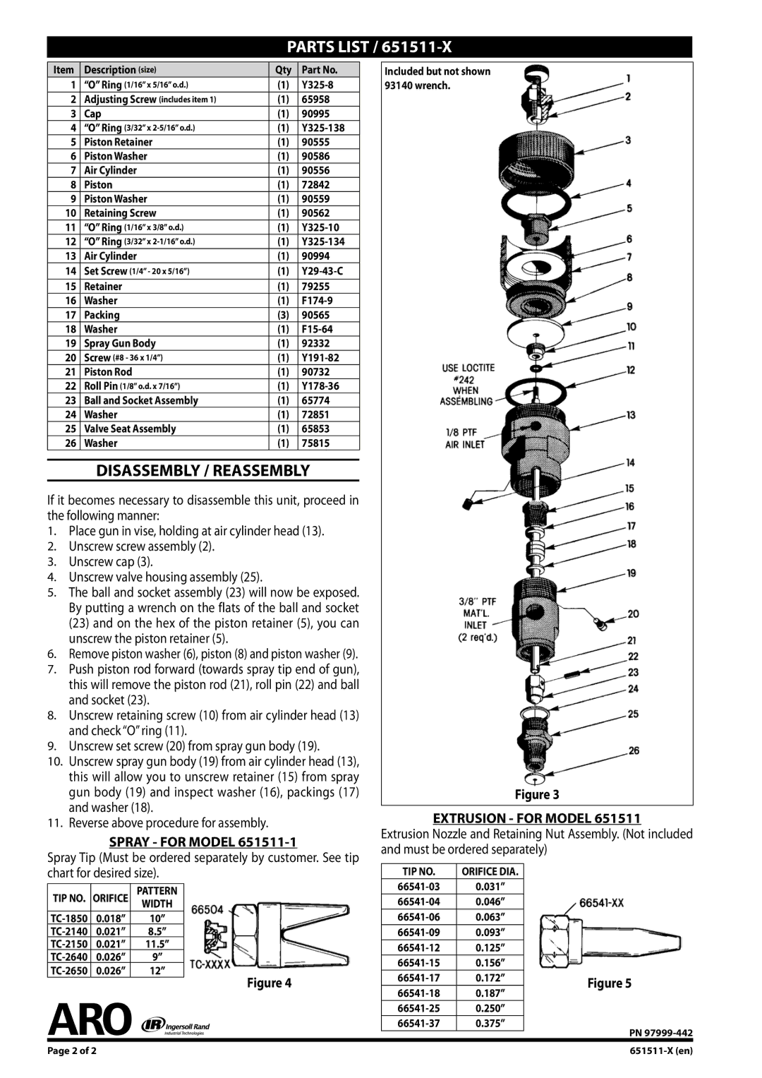
If it becomes necessary to disassemble this unit, proceed in the following manner:

1.Place gun in vise, holding at air cylinder head (13).

2.Unscrew screw assembly (2).

3.Unscrew cap (3).

4.Unscrew valve housing assembly (25).

5.The ball and socket assembly (23) will now be exposed. By putting a wrench on the flats of the ball and socket (23) and on the hex of the piston retainer (5), you can unscrew the piston retainer (5).

6.Remove piston washer (6), piston (8) and piston washer (9).

7.Push piston rod forward (towards spray tip end of gun), this will remove the piston rod (21), roll pin (22) and ball and socket (23).

8.Unscrew retaining screw (10) from air cylinder head (13) and check “O” ring (11).

9.Unscrew set screw (20) from spray gun body (19).

10.Unscrew spray gun body (19) from air cylinder head (13), this will allow you to unscrew retainer (15) from spray gun body (19) and inspect washer (16), packings (17) and washer (18).

11.Reverse above procedure for assembly.

SPRAY - FOR MODEL 651511-1

Spray Tip (Must be ordered separately by customer. See tip chart for desired size).

TIP NO.

ORIFICE

PATTERN


WIDTH


TC-1850

0.018”

10”


TC-2140

0.021”

8.5”


TC-2150

0.021”

11.5”


TC-2640

0.026”

9”


TC-2650

0.026”

12”

Figure 4


Included but not shown 93140 wrench.

Figure 3

EXTRUSION - FOR MODEL 651511

Extrusion Nozzle and Retaining Nut Assembly. (Not included and must be ordered separately)

TIP NO.

ORIFICE DIA.


66541-03

0.031”


66541-04

0.046”


66541-06

0.063”


66541-09

0.093”


66541-12

0.125”


66541-15

0.156”


66541-17

0.172”

Figure 5

66541-18

0.187”


66541-25

0.250”


66541-37

0.375”

PN 97999-442


Page of 2

651511-X (en)

Page 2
Image 2
Ingersoll-Rand 651511-X operating instructions Parts List, Disassembly / Reassembly

651511-X specifications

The Ingersoll-Rand 651511-X is a prominent model in the realm of air compressors, designed with a robust suite of features that make it ideal for both industrial and commercial applications. Known for its reliability and efficient performance, this air compressor is often employed across a variety of sectors including manufacturing, construction, and automotive services.

One of the standout attributes of the Ingersoll-Rand 651511-X is its powerful engine, which is engineered to deliver exceptional air output with consistent pressure. The unit boasts a high-capacity tank that enhances its efficiency, reducing the frequency of refills and allowing for extended operation periods. This means fewer interruptions and increased productivity for heavy-duty tasks.

In terms of technology, the 651511-X incorporates advanced oil-flooded rotary screw technology. This design minimizes wear and tear on the compressor components, thus extending the lifespan of the unit. Additionally, the oil-flooded system not only cools the compressor, but it also lubricates moving parts, ensuring smooth operation while maintaining optimal performance even under heavy loads.

The user-friendly controls and digital display facilitate ease of operation, allowing users to monitor the compressor's performance in real-time. Maintenance is also streamlined due to the unit’s modular design, which provides easy access to key components for servicing, minimizing downtime and reducing maintenance costs.

For safety, the Ingersoll-Rand 651511-X is equipped with comprehensive protection systems that prevent overheating and over-pressurization, ensuring that both the equipment and operators are safeguarded during operations. Additional features may include integrated lift handles and wheels, which enhance its portability, making it easy for operators to reposition the unit as needed on job sites.

Overall, the Ingersoll-Rand 651511-X exemplifies efficiency and durability, making it a trusted choice for professionals seeking a high-performance air compressor that can meet the demanding requirements of various applications. Whether for powering pneumatic tools or providing a steady stream of compressed air for other purposes, the 651511-X stands out as a reliable partner in achieving operational excellence.