Ingersoll-Rand 6696X-X manual Lower Pump Disassembly Lower Pump Reassembly, 15 ``O ring

Models: 6696X-X

1 4
Download 4 pages 5.08 Kb
Page 4
Image 4

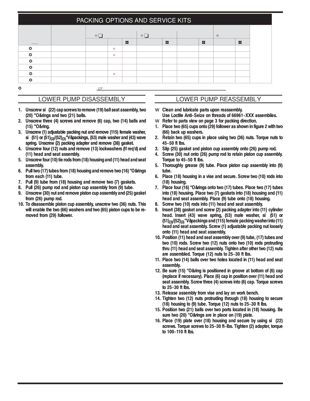
PACKING OPTIONS AND SERVICE KITS

LOWER PUMP

SERVICE KIT


UPPER PACKING


LOWER PKG


51 (X) ``V" PACKING

52 (3) ``V" PACKING

70 PACKING

65 (2) PACKING


6696X-XXX

63724X-XX3

PART NO

QTY.

MT'L

PART NO

MT'L

PART NO

MT'L

PART NO

MT'L


-1X3 ￿

637240-F43

93688-1

(6)

[L]


92963-1

[L]


-8X3 ￿

637240-F43

93688-4

(3)

[UH]

93688-1

[L]


92963-4

[UH]


-A33

￿

637241-C33


93355-1

[UH]

92963-4

[UH]


-B33

￿

637241-C33


93355-1

[UH]

92963-4

[UH]


-C13

￿, C43

637240-C43

93688-4

(6)

[UH]


92963-4

[UH]


-C33

￿

637241-C33


93355-1

[UH]

92963-4

[UH]


￿AS OF MAY 15, 1995 NO LONGER AVAILABLE // EXAMPLE: 66960-113 is replaced by 66960-F43 & Ser<ice kit is 637240-F43

LOWER PUMP DISASSEMBLY


LOWER PUMP REASSEMBLY

1.Unscrew six (22) cap screws to remove (19) ball seat assembly, two

(20)``O￿ rings and two (21) balls.

2.Unscrew three (4) screws and remove (6) cap, two (14) balls and

(15)``O￿ ring.

3.Unscrew (1) adjustable packing nut and remove (115) female washer,

six (51) or (51)(3)/(52)(3)``V￿ packings, (53) male washer and (43) wave spring. Unscrew (2) packing adapter and remove (38) gasket.

4.Unscrew four (12) nuts and remove (13) lockwashers (If req'd) and

(11)head and seat assembly.

5.Unscrew four (10) tie rods from (18) housing and (11) head and seat assembly.

6.Pull two (17) tubes from (18) housing and remove two (16) ``O￿ rings from each (11) tube.

7.Pull (9) tube from (18) housing and remove two (7) gaskets.

8.Pull (26) pump rod and piston cup assembly from (9) tube.

9.Unscrew (30) nut and remove piston cup assembly and (25) gasket from (26) pump rod.

10.To disassemble piston cup assembly, unscrew two (36) nuts. This will enable the two (66) washers and two (65) piston cups to be re< moved from (29) follower.

Clean and lubricate parts upon reassembly.

Use Loctite Anti-Seize on threads of 66961-XXX assemblies.

Refer to parts view on page 3 for packing direction.

1.Place two (65) cups onto (29) follower as shown in figure 2 with two

(66)back up washers.

2.Retain two (65) cups in place using two (36) nuts. Torque nuts to 45-50 ft lbs.

3.Slip (25) gasket and piston cup assembly onto (26) pump rod.

4.Screw (30) nut onto (26) pump rod to retain piston cup assembly. Torque to 45-50 ft lbs.

5.Thoroughly grease (9) tube. Place piston cup assembly into (9) tube.

6.Place (18) housing in a vise and secure. Screw two (10) rods into

(18)housing.

7.Place four (16) ``O￿ rings onto two (17) tubes. Place two (17) tubes into (18) housing. Place two (7) gaskets into (18) housing and (11) head and seat assembly. Place (9) tube onto (18) housing.

8.Screw two (10) rods into (11) head and seat assembly.

9.Insert (38) gasket and screw (2) packing adapter into (11) cylinder head. Insert (43) wave spring, (53) male washer, six (51) or

(51)(3)/(52)(3)``V￿ packings and (115) female packing washer into (11) head and seat assembly. Screw (1) adjustable packing nut loosely onto (11) head and seat assembly.

10.Position (11) head and seat assembly over (9) tube, (17) tubes and two (10) rods. Screw two (12) nuts onto two (10) rods protruding thru (11) head and seat assembly. Tighten after other two (12) nuts are assembled. Torque (12) nuts to 25-30 ft lbs.

11.Place two (14) balls over two holes located in (11) head and seat assembly.

12.Be sure (15) ``O￿ ring is positioned in groove at bottom of (6) cap (replace if necessary). Place (6) cap in position over (11) head and seat assembly. Screw three (4) screws into (6) cap. Torque screws to 25-30 ft lbs.

13.Release assembly from vise and lay on work bench.

14.Tighten two (12) nuts protruding through (18) housing to secure

(18)housing to (9) tube. Torque (12) nuts to 25-30 ft lbs.

15.Position two (21) balls over two ports located in (18) housing. Be sure two (20) ``O￿ rings are in place on (19) plate.

16.Place (19) plate over (18) housing and secure by using six (22) screws. Torque screws to 25-30 ft-lbs. Tighten (2) adapter, torque to 100-110 ft lbs.


PN 97999-051


PAGE 4 OF 4

6696X-X

Page 4
Image 4
Ingersoll-Rand 6696X-X Lower Pump Disassembly Lower Pump Reassembly, Service KIT Upper Packing Lower PKG, 15 ``O ring

6696X-X specifications

The Ingersoll-Rand 6696X-X is a robust, high-performance air compressor designed to meet the demands of various industrial applications. Renowned for its reliability and efficiency, the 6696X-X has established itself as a go-to option for businesses requiring durable and dependable air power solutions.

One of the standout features of the 6696X-X is its powerful motor, which allows it to deliver a high output of compressed air, making it suitable for tasks ranging from powering pneumatic tools to supporting heavy machinery. This air compressor operates with a maximum pressure rating that ensures a consistent supply of air under demanding conditions, providing users with the efficiency they need to keep operations running smoothly.

The 6696X-X utilizes advanced technologies such as variable speed drive (VSD) which optimizes energy consumption by adjusting the motor speed according to the demand for compressed air. This feature not only reduces operational costs but also extends the life of the components by minimizing wear and tear. Furthermore, its integrated control systems offer real-time monitoring and diagnostics, enabling users to oversee performance metrics and scheduled maintenance, reducing the risk of unexpected downtime.

Designed for ease of use, the 6696X-X incorporates ergonomically placed controls and intuitive interfaces that allow operators to manage the equipment with minimal training. The compressor's compact design makes it easy to integrate into existing setups, maximizing floor space while maintaining performance.

Durability is at the core of the 6696X-X's design. Constructed from high-quality materials, it is built to withstand harsh environments, ensuring longevity even in the most demanding conditions. The unit is also equipped with advanced filtration systems that maintain air quality, reducing the risk of contamination in applications where clean air is critical.

In summary, the Ingersoll-Rand 6696X-X air compressor stands out with its powerful performance, energy-efficient technologies, and user-friendly design. Its combination of reliability, enhanced durability, and operational efficiency makes it an ideal choice for industries that require a dependable source of compressed air to ensure productivity and performance. With its advanced features, the 6696X-X continues to set a standard in the air compressor market, catering to the evolving needs of modern industrial applications.