Assembly
General Instructions
1.Always press on the inner ring of a ball–type bearing when installing the bearing on a shaft.
2.Always press on the outer ring of a ball–type bearing when pressing the bearing into a bearing recess.
3.Whenever grasping a tool or part in a vise, always use leather–covered or copper–covered vise jaws. Take extra care not to damage threads or distort housings.
4.Except for bearings, clean every part and wipe every part with a thin film of oil before installation.
5.Check every bearing for roughness. If an open bearing must be cleaned, wash it thoroughly clean suitable solution and dry with a clean cloth. Sealed or shielded bearings should not be cleaned. Work grease into every bearing before installation.
6.Apply a film of O–ring lubricant to every O–ring before installation.
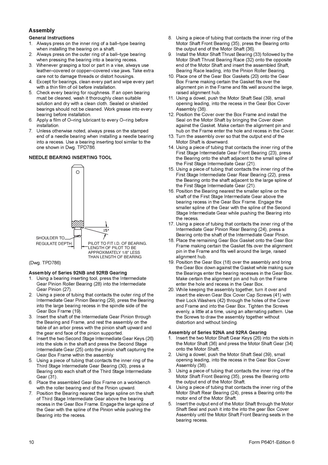
7.Unless otherwise noted, always press on the stamped end of a needle bearing when installing a needle bearing into a recess. Use a bearing inserting tool similar to the one shown in Dwg. TPD786.
NEEDLE BEARING INSERTING TOOL
SHOULDER TO | |
REGULATE DEPTH | PILOT TO FIT I.D. OF BEARING. |
| LENGTH OF PILOT TO BE |
| APPROXIMATELY 1/8” LESS |
| THAN LENGTH OF BEARING |
(Dwg. TPD786)
Assembly of Series 92NB and 92RB Gearing
1.Using a bearing inserting tool, press the Intermediate Gear Pinion Roller Bearing (28) into the Intermediate Gear Pinion (27).
2.Using a piece of tubing that contacts the outer ring of the Intermediate Gear Pinion Bearing (29), press the Bearing into the large bearing recess in the spindle side of the Gear Box Frame (19).
3.Insert the shaft of the Intermediate Gear Pinion through the Bearing and Frame, and rest the assembly on the table of an arbor press with the pinion shaft upward and the gear end face of the pinion supported.
4.Insert the two Second Stage Intermediate Gear Keys (26) into the slots in the shaft and press the Second Stage Intermediate Gear (25) onto the pinion shaft capturing the Gear Box Frame within the assembly.
5.Using a piece of tubing that contacts the inner ring of the Third Stage Intermediate Gear Bearing (30), press a Bearing onto each shaft of the Third Stage Intermediate Gear (31).
6.Place the assembled Gear Box Frame on a workbench with the roller bearing end of the Pinion upward.
7.Position the Bearing nearest the large spline on the shaft of Third Stage Intermediate Gear above the bearing recess in the Gear Box Frame. Engage the large spline of the Gear with the spline of the Pinion while pushing the Bearing into the recess.
8.Using a piece of tubing that contacts the inner ring of the Motor Shaft Front Bearing (35), press the Bearing onto the output end of the Motor Shaft (36).
9.Install the Motor Shaft Thrust Bearing (33) followed by the Motor Shaft Thrust Bearing Race (32) onto the opposite end of the Motor Shaft and insert the assembled Shaft, Bearing Race leading, into the Pinion Roller Bearing.
10.Place one of the Gear Box Gaskets (20) onto the Gear Box Frame making certain the Gasket fits over the alignment pin in the Frame and fits well around the large, raised alignment hub.
11.Using a dowel, push the Motor Shaft Seal (39), small opening leading, into the recess in the Gear Box Cover Assembly (38).
12.Position the Cover over the Box Frame and install the Seal on the Motor Shaft by bringing the Cover down against the Gasket. Make certain the alignment pin and hub on the Frame enter the hole and recess in the Cover.
13.Turn the assembly over so that the output end of the Motor Shaft is downward.
14.Using a piece of tubing that contacts the inner ring of the First Stage Intermediate Gear Front Bearing (23), press the Bearing onto the shaft adjacent to the small spline of the First Stage Intermediate Gear (21).
15.Using a piece of tubing that contacts the inner ring of the First Stage Intermediate Gear Rear Bearing (22), press the Bearing onto the shaft adjacent to the large spline of the First Stage Intermediate Gear (21).
16.Position the Bearing nearest the smaller spline on the shaft of the First Stage Intermediate Gear above the bearing recess in the Gear Box Frame. Engage the smaller spline of the Gear with the spline of the Second Stage Intermediate Gear while pushing the Bearing into the recess.
17.Using a piece of tubing that contacts the inner ring of the Intermediate Gear Pinion Rear Bearing (24), press a Bearing onto the shaft of the Intermediate Gear Pinion.
18.Place the remaining Gear Box Gasket onto the Gear Box Frame making certain the Gasket fits over the alignment pin in the Frame and fits well around the large, raised alignment hub.
19.Position the Gear Box (18) over the assembly and bring the Gear Box down against the Gasket while making sure the Bearings enter the bearing recesses in the Gear Box. Make certain the alignment pin and hub on the Frame enter the hole and recess in the Gear Box.
20.While keeping the assembly together, turn it over and insert the eleven Gear Box Cover Cap Screws (41) with their Lock Washers (42) through the holes of the Cover and Frame and into the Gear Box. Tighten the Screws evenly, a little at a time, using an alternating pattern. Use the Screws to draw the assembly together without distortion and without binding.
Assembly of Series 92NA and 92RA Gearing
1.Insert the two Motor Shaft Gear Keys (26) into the slots in the Motor Shaft (36) and press the Motor Shaft Gear (34) onto the Motor Shaft.
2.Using a dowel, push the Motor Shaft Seal (39), small opening leading, into the recess in the Gear Box Cover Assembly (38).
3.Using a piece of tubing that contacts the inner ring of the Motor Shaft Front Bearing (35), press the Bearing onto the output end of the Motor Shaft.
4.Using a piece of tubing that contacts the inner ring of the Motor Shaft Rear Bearing (24), press a Bearing onto the motor end of the Motor Shaft.
5.Insert the output end of the Motor Shaft through the Motor Shaft Seal and push it into the into the gear Box Cover Assembly until the Motor Shaft Front Bearing seats in the bearing recess.