
AF0623SXXXXXX-XX-X specifications
The Ingersoll-Rand AF0623SXXXXXX-XX-X is a cutting-edge air filter designed for industrial applications, known for its remarkable efficiency and durability. This model effectively addresses the needs of various sectors, including manufacturing, automotive, and food processing, where clean air is critical for optimal equipment performance and product quality.One of the main features of the AF0623SXXXXXX-XX-X is its advanced filtration technology. The filter employs a multi-layer design that captures particles of varying sizes, from dust and dirt to oil mist and water droplets, ensuring that the compressed air entering machinery is pure and free from contaminants. This not only enhances the operational efficiency of air tools and pneumatic systems but also significantly extends the life of the equipment by reducing wear and tear.
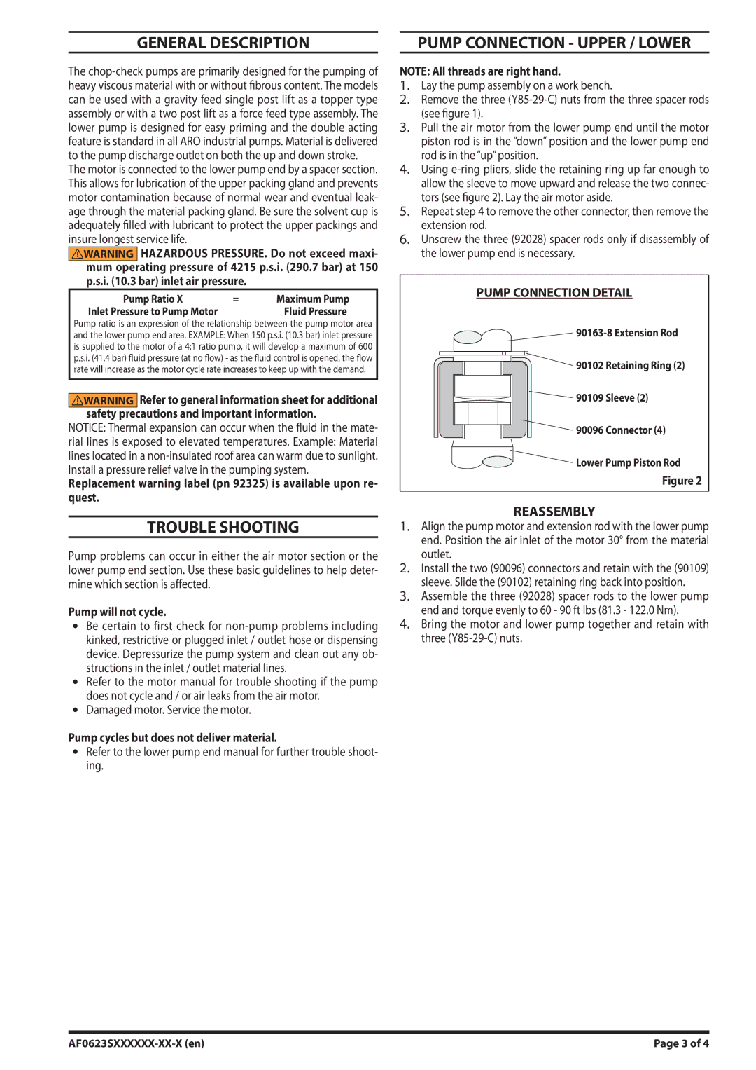
Moreover, the AF0623SXXXXXX-XX-X boasts a high flow rate, allowing for seamless operation even in high-demand environments. Its robust construction is engineered to withstand extreme conditions, ensuring reliability even in harsh industrial settings. This model is also designed for easy installation and maintenance, minimizing downtime and operational disruptions.
Another significant characteristic of the Ingersoll-Rand AF0623SXXXXXX-XX-X is its low-pressure drop design. By maintaining optimal airflow while effectively filtering out unwanted particles, it contributes to energy savings, allowing facilities to operate more sustainably. This feature is particularly important in today's eco-conscious market, where businesses seek to reduce their environmental footprint while also managing operational costs.
The filter is compatible with a wide range of Ingersoll-Rand equipment, making it a versatile choice for various applications. It also meets stringent industry standards, ensuring that it can handle the demands of any commercial or industrial setting.
In summary, the Ingersoll-Rand AF0623SXXXXXX-XX-X air filter combines advanced filtration technology, high flow capacity, and enhanced durability to provide a reliable solution for maintaining clean air in industrial applications. Its design not only promotes the longevity of equipment but also facilitates energy efficiency, making it an essential component for any operation prioritizing performance and sustainability.