LXD970A Demo Board for 10/100, LXD970A specifications
The Intel LXD970A and the LXD970A Demo Board represent significant advancements in networking technology, designed to provide efficient solutions for both developers and engineers looking to implement 10/100 Mbps networking solutions. These products serve as an excellent choice for various applications, including embedded systems, industrial automation, and networking equipment.At the core of the LXD970A is its robust support for both 10BASE-T and 100BASE-TX Ethernet standards, allowing users to seamlessly integrate into existing networks while also supporting higher bandwidth requirements. This dual capability not only enhances flexibility but also ensures compatibility with a wide range of legacy and modern devices.
One of the key features of the LXD970A is its advanced integrated design, featuring a built-in media access control (MAC) layer, which streamlines the overall design by reducing the need for additional components. This integration results in lower power consumption, which is crucial for battery-powered applications as well as environmentally conscious designs.
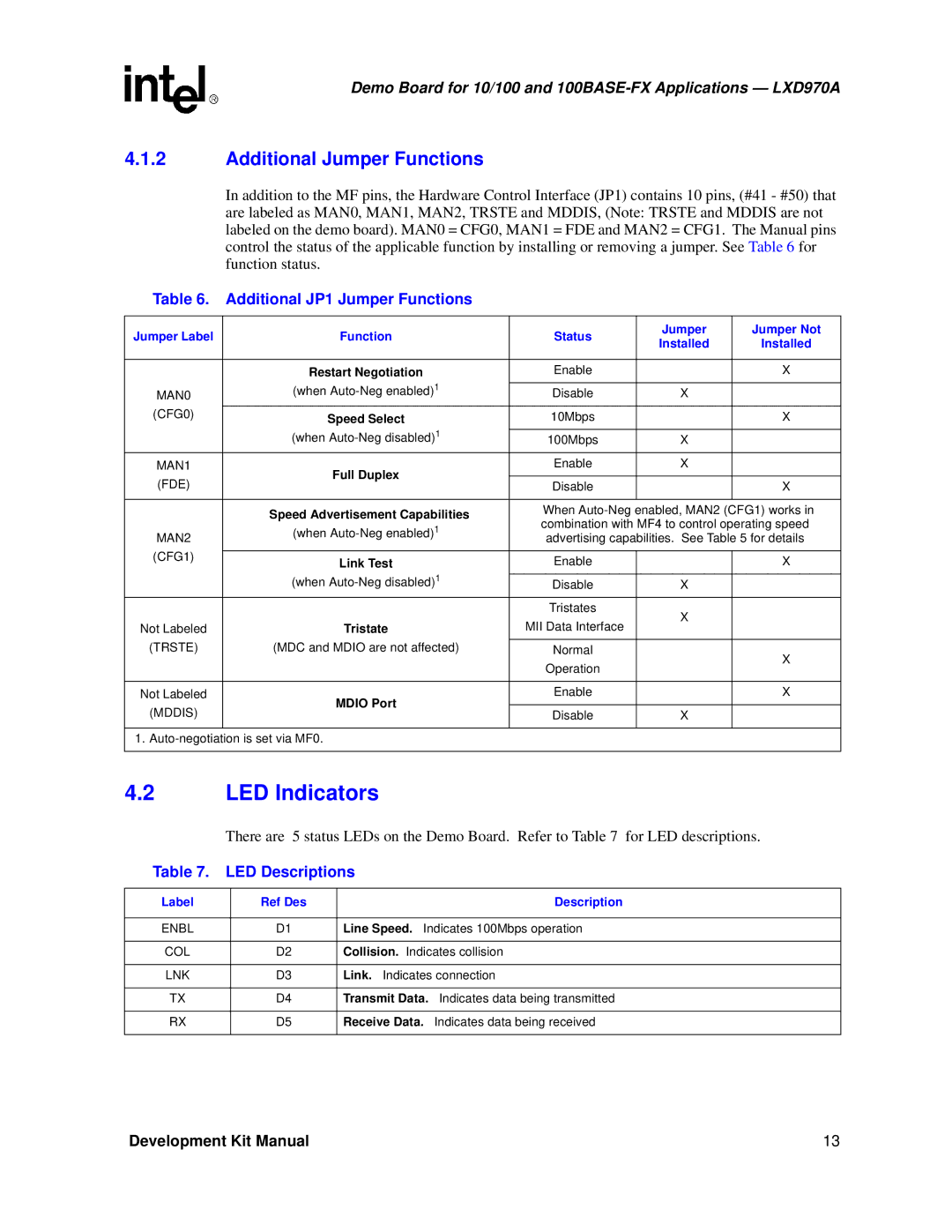
The LXD970A Demo Board acts as a comprehensive platform for developers. With easy access to all the necessary interfaces, including GPIO (General Purpose Input/Output) and a simple Ethernet connector, the demo board provides an out-of-the-box experience, enabling users to test and develop applications rapidly. Comprehensive documentation and sample code assist in accelerating the development process.
Moreover, with a focus on security, the LXD970A supports various protocols and features designed to protect data integrity and prevent unauthorized access. This is particularly important for applications that handle sensitive information across networks.
The Intel LXD970A also supports Automatic MDI/MDI-X crossover detection, eliminating the need for crossover cables and simplifying the network setup. This feature enhances ease of use and makes it suitable for various networking environments, ensuring that installations are trouble-free and efficient.
In addition to its technical specifications, the LXD970A is also designed with durability in mind, making it suitable for industrial environments where rugged performance is essential. Its operational temperature range and reliability standards are tailored to meet the demands of harsh conditions often found in industrial applications.
Overall, the Intel LXD970A and its accompanying demo board are invaluable tools for developers and engineers seeking to leverage the benefits of high-speed networking while maintaining flexibility and compatibility across a broad spectrum of devices and applications. With its blend of advanced features, low power design, and extensive support, the LXD970A stands out as a significant asset in the toolkit of any networking professional.

